The concept of alternating current
Foreword.
Before You Begin Talk about counters, remember that these are electrical devices, and in the following description I will rush with all sorts of clever terms. Of course, if you have an electrical education, you can immediately skip this part. And if you know about electricity only that if you plug the iron into the outlet it starts to bask, then I strongly recommend that you read this chapter, so that later you do not feel like a stranger at the universal celebration of life. The chapter is taken from the site of Voropaev EG. "Electrical Engineering" , there are many more of these, I recommend reading for self-education, it is written quite popular (at the level of the first year of the electrotechnical school).
So:
Definition: Variables are currents and voltages varying in time, in magnitude and direction. Their value at any time is called the instantaneous value. The instantaneous values are denoted by small letters: i, u, e, p.
Currents whose values are repeated at regular intervals are called periodic currents.
The smallest time interval through which their repetitions are observed is called the period and is denoted by the letter T. The quantity inverse to the period is called the frequency, i.e.
![]() And measured in hertz (Hz).
Value
And measured in hertz (Hz).
Value
![]() Is called the angular frequency of the alternating current, it shows the change in the phase of the current per unit time and is measured in radians divided by a second
Is called the angular frequency of the alternating current, it shows the change in the phase of the current per unit time and is measured in radians divided by a second
The maximum value of an alternating current or voltage is called the amplitude.
It is denoted by large letters with the index '' m '' (for example, I m ).
There is also a concept of the effective value of alternating current (I).
Quantitatively, it is:

It should be noted that the effective value of the voltage is less than the maximum value.
Alternating current can be mathematically written as:

Here, the index expresses the initial phase. If the sinusoid starts at the point of intersection of the coordinate axes, then = 0, then
![]()
The initial current value can be to the left or right of the ordinate axis.
Then the initial phase will be leading or lagging.
1.2. RESISTANCE IN AC CIRCUITS.
The electric current in the conductors is continuously connected with the magnetic and electric fields.
Elements characterizing the transformation of electromagnetic energy into heat are called active resistances (denoted by R).
The elements associated with the presence of only a magnetic field are called inductivities.
Elements associated with the presence of an electric field are called capacitances.
Typical representatives of active resistances are resistors, incandescent lamps, electric furnaces, etc.
Inductors are provided with relay coils, motor windings and transformers.
Inductive resistance is calculated by the formula:

Where L is the inductance.
Capacitors, long power lines, etc., have capacitance.
The capacitive resistance is calculated by the formula:

Where C is the capacity.
Real consumers of electrical energy can have a complex value of resistances.
In the presence of R and L, the value of the total resistance Z is calculated by the formula:
![]()
Similarly, Z is calculated for the chain R and C:
![]()
Consumers with R, L, C have a total resistance:
![]()
1.3.
CONSEQUENTIAL CONNECTION OF ACTIVE RESISTANCE R,
CONDENSER WITH AND INDUCTIVITY L
Consider a circuit with active, inductive and capacitive resistances connected in series (Figure 1.3.1).
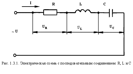
To analyze the circuit, we decompose the voltage of the network U into three components:
U R - voltage drop on the active resistance,
U L - voltage drop on the inductive resistance,
U C - voltage drop across the capacitive resistance.
The current in circuit I will be common for all elements:
![]()
The check is made by the formula:
![]()
It should be noted that the stresses on individual sections of the circuit do not always coincide in phase with the current I.
Thus, at an active resistance, the voltage drop coincides in phase with the current, on the inductive one it outruns the current by 90 ° and on the capacitive one it lags behind it by 90 °.
Graphically, this can be shown on a vector diagram (Figure 1.3.2).
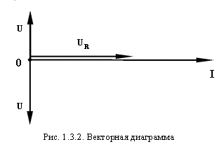
The three vectors of voltage drop shown above can be geometrically combined into one (Figure 1.3.3).
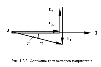
In such a combination of elements, active-inductive or active-capacitive load patterns of the circuit are possible.
Consequently, the phase shift has both a positive and a negative sign.
An interesting mode is when = 0.
In this case
![]()
This mode of operation of the circuit is called stress resonance.
The impedance at the resonance of the voltages has a minimum value:
![]()
, And at a given voltage U the current I can reach a maximum value.
From condition
![]() Determine the resonant frequency
Determine the resonant frequency
![]()
The phenomenon of voltage resonance is widely used in radio engineering and in certain industrial installations.
1.4.
CONDENSER AND COIL PARALLEL CONNECTION,
WITH ACTIVE RESISTANCE AND INDUCTIVITY
Consider a circuit of parallel connection of a capacitor and a coil with active resistance and inductance (Figure 1.4.1).
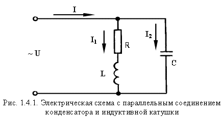
In this scheme, the common parameter for the two branches is the voltage U. The first branch - the inductive coil - has the active resistance R and the inductance L. The resulting resistance Z 1 and current I 1 are determined by the formula:
![]() , Where
, Where
![]()
Since the resistance of this branch is complex, the current in the branch lags in phase from the voltage to the angle.
![]()
We show this on a vector diagram (Figure 1.4.2).
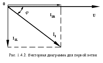
Project the current vector I 1 on the coordinate axis. The horizontal component of the current will be the active component I 1R , and the vertical component I 1L . The quantitative values of these components will be:
![]() Where
Where
![]()
The second branch includes a capacitor. His resistance
![]()
This current is ahead of the phase by 90 °.
To determine the current I in the unbranched part of the chain, we use the formula:
![]()
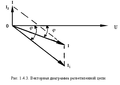
Its value can also be obtained graphically by adding the vectors I 1 and I 2 (Figure 1.4.3)
The angle of the shift between the current and voltage is denoted by the letter j .
Here, different modes are possible in the operation of the circuit.
At = + 90 ° the capacitive current will prevail, at = -90 ° - inductive.
A mode is possible when = 0, i.e.
The current in the unbranched portion of chain I will be of an active nature.
This will happen in the case when I 1L = I 2 , i.e.
When the reactive components of the current in the branches are equal.
On a vector diagram this will look like this (Figure 1.4.4):
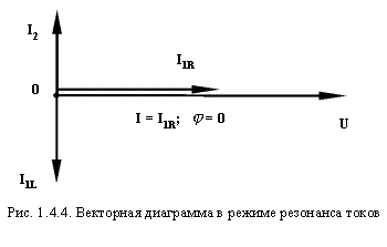
This mode is called current resonance.
Just like in the case of resonance voltage, it is widely used in radio engineering.
The case of parallel connection R, L and C discussed above can also be analyzed from the point of view of increasing cos j for electrical installations.
It is known that cos j is a technical and economic parameter in the operation of electrical installations.
It is determined by the formula:
![]() , Where
, Where
P - active power of electrical installations, kW,
S - total power of electrical installations, kW.
In practice, cos j is determined by removing from the counters the readings of active and reactive energy, and by dividing one indication by another, one obtains tg j .
Next, cos j is found from the tables.
The more cos j , the more economical the power system works, because with the same values of current and voltage (for which the generator is designed) it can receive a large active power.
A decrease in cos j results in incomplete use of the equipment and at the same time the efficiency of the installation decreases.
Tariffs for electricity provide for a lower cost of 1 kilowatt-hour at high cos j , in comparison with low.
Activities to increase cos include:
- prevention of idling electrical equipment,
- full load of electric motors, transformers, etc.
In addition, at cos j , the connection to the network of static capacitors has a positive effect.


Comments
Commenting on, remember that the content and tone of your message can hurt the feelings of real people, show respect and tolerance to your interlocutors even if you do not share their opinion, your behavior in the conditions of freedom of expression and anonymity provided by the Internet, changes Not only virtual, but also the real world. All comments are hidden from the index, spam is controlled.