Great theorists and great practices, or a story about how the radio was created. Part 2
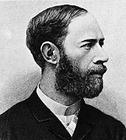
Spark generator of electromagnetic volts of Henry Hertz
In 1886 - 1889 Henry Hertz built a spark generator of electromagnetic waves and investigated their properties. The device of the spark generator deserves a more detailed description.
Its basis is the oscillatory circuit. But the oscillations in the real loop quickly decay, and in order to maintain a series of oscillations, it is necessary to recharge the capacitor again and again and switch it from the voltage source to the coil.
This fast-acting switch serves as a spark gap between two metal balls. Spark produces an induction coil, or a Rumkorp coil.
 Now very few people know what it is, and the more it is difficult to imagine the device of an induction coil. But more than half a century it was one of the most common devices in electrical engineering. (A variation of the induction coil and is still used in car ignition systems.)
The battery current, passing through the primary winding of the induction coil, magnetizes its iron core, which attracts the movable contact, and the circuit breaks. The magnetic field disappears and the contact closes again. The frequency of current interruptions is small and is 102 ... 103 times per second. But the most interesting happens at the moment of breaking the chain.
In the coils of the induction coil, there is an EMF of self-induction, proportional to the rate of change of the magnetic flux. This speed is very high, because the contacts open almost instantly. As a result, at the time of opening, a voltage pulse appears at the terminals of the primary winding, several tens of times higher than the battery voltage!
For example, with a voltage of 12 V, it is not difficult to get a voltage pulse of 300 ... 400 V. The secondary winding contains much more turns, and the voltage pulse at its terminals can reach several thousand volts or even tens of kilovolts. The capacitor of the circuit is also charged to the same voltage.
The spark gap is adjusted so that it breaks through at a voltage close to the maximum developed by the induction coil. The jumped spark closes the circuit of the oscillating LC circuit, and a series of damped oscillations occurs in it.
Hertz's vibrator
So, the induction coil allowed to excite a series of damped oscillations of high frequency. But how to radiate them into space in the form of waves?
Heinrich Hertz believed, as it follows from Maxwell's equations, that the faster the electric and magnetic fields change, the more effectively the waves radiate. In an effort to increase the frequency of oscillation of the circuit, Hertz left only one coil in the coil of the circuit, and reduced the area of the plates of the capacitor to the limit. The result is a vibrator consisting of two rods with a spark gap between them.
It turned out that the Hertz vibrator effectively emits waves with a length equal to twice the length of the vibrator. Now we know that the Hertzian vibrator is an ordinary half-wave dipole. Look at any roof, and you will see television antennas, which are a system of dipoles.
The receiver of the oscillations was another dipole with very close spaced beams of the spark gap. When a spark jumped in the transmitting dipole, a tiny spark could be seen in the reception room! Thus, the transmission of electromagnetic waves of the radio range over a distance of several meters was carried out experimentally. It turned out that reception is most effective when the receiving vibrator is tuned in resonance with the transmitter. The lengths of the vibrators are the same.
Hertz's experiments, carried out in the years 1887-1888, aroused great interest among physicists and engineers. Many began to repeat, modify and improve them. PN Lebedev , a remarkable Russian physicist who discovered, in particular, the pressure of light, constructed a vibrator for wavelengths up to three centimeters (in Hertz's experiments, the wavelength was about three meters).
They were very tiny vibrators! The phenomena of reflection and refraction of electromagnetic waves at the interface between different media were investigated. We observed the reflection of waves from a metal sheet, the refraction of waves by a prism made of a dielectric.
Significantly more powerful electromagnetic oscillations, but a lower frequency, allowed the transformer Nikola Tesla , the secondary winding of which was tuned to resonance with the primary. Since there was no condenser in the secondary winding, the number of turns was much larger than in the primary, which provided voltages up to a million volts on the vibrator!
The receiver of electromagnetic waves of Alexander Stepanovich Popov
Finally we came very close to our story by the time the radio was invented. Of course, you know who did it. Our compatriot, the teacher of physics of mine officers' classes in Kronstadt Alexander Stepanovich Popov .
He managed to design a receiver of electromagnetic waves, which has sufficient sensitivity for practical purposes. Let us recall the receiving Hertz vibrator. In order for the spark to penetrate in its spark gap, it is necessary that the electromagnetic wave develop a voltage of several hundred volts in it. And this means that the intensity of the electromagnetic wave field should also be about hundreds of volts per meter (after all, the length of the vibrator was close to 1 m).
The voltage in the vibrator can be calculated very simply: the intensity of the electric field of the wave must be multiplied by the effective (effective) length of the vibrator. Usually it is approximately 0.7 geometric length of the vibrator. Such strong fields create only close discharges of lightning.
One day I unhurriedly detached the antenna feeder from my amateur transmitter, admiring the window of a beautiful thundercloud. The lightning flashed in the cloud, and at the same moment, between the terminals of the antenna and the grounding, which I had in my hands, a bluish spark a few centimeters long slipped through with a dry crack! Well, the conclusions were with thick insulation.
With trembling hands, I still connected these conclusions, grounding the antenna, and began to recall GV Richman , an associate of MV Lomonosov , who died during a thunderstorm during experiments with a metal rod on the roof (later this rod, only grounded, began to be called Lightning rod). Since then, I always turn off the antenna long before the thunderstorm approaches, although all the designs of my antennas have reliable lightning protection.
But back to the receiver of AS Popov. Instead of a spark gap in the receiving dipole, Popov used a coherer, a device invented not long before by the Frenchman E. Branly.
The coherer was a glass tube with two terminals, between which iron sawdust was poured. Because of the thinnest layer of oxide on the surface of the sawdust, the resistance of the coherer is large, but only as long as there is no voltage at its terminals, regardless of alternating or direct current.
 As soon as the voltage induced by the electromagnetic wave is applied, the resistance of the coherer drops sharply. This is due to the action of the smallest sparks that break through the oxide layer between the sawdust and, as it were, weld the filings together. To destroy the formed bridges for electric current, the coherer had to be shaken enough.
To the coherer oscillations induced by the received wave in the receiving vibrator were introduced. The next important element of the AS Popov receiver is a direct current relay amplifier. A relatively weak current through the coherer activated the sensitive relay, whose contacts closed the circuit of the electric bell. The device of the bell in many respects was similar to the device of the Rumkorff coil , there was no only a secondary winding.
The bell of the bell in the receiver Popov hit not only on the bell, but, bouncing off, also on the coherer. Thus, the coherer was automatically shaken after receiving each electromagnetic pulse and was ready to receive the next one.
Another important improvement in the receiver of Popov was the use of a receiving antenna. After all, the longer the antenna wire, the more voltage is induced in it by the electromagnetic wave.
The wire antenna, stretched to the nearest tree or to the roof of the house, is like one half of the Hertzian vibrator. But we need a second half, a counterbalance. The role of the counterweight is successfully carried out by grounding. The currents that would have to flow in a counterbalance can simply spread over the surface and in the earth's thickness, because the usual, fairly humid soil conducts electricity well.
Finally the receiver was ready. But there was not a transmitter yet! It was possible to receive only radio signals of natural origin. They are generated at each lightning strike, because lightning is a gigantic spark, and the ionized gas channel formed during a discharge perfectly conducts electric current and serves as a transmitting vibrator.
AS Popov called his receiver a thunder-storm. With the external antenna connected, it was possible to record thunderstorms at distances of up to 30 km. Each discharge of lightning was accompanied by a short tricking of the bell in the receiver!
This device AS Popov demonstrated May 7, 1895 at a meeting of the Russian Physico-Chemical Society. Since 1945, every year on May 7 is celebrated as the birthday of the radio .
Author of the article: Polyakov VT (from the book "Dedication to Radio Electronics")
<< Previous [1] 2 Next >>

Comments
When commenting on, remember that the content and tone of your message can hurt the feelings of real people, show respect and tolerance to your interlocutors even if you do not share their opinion, your behavior in the conditions of freedom of expression and anonymity provided by the Internet, changes Not only virtual, but also the real world. All comments are hidden from the index, spam is controlled.