
The emergence and initial period of the development of electrical machines
The discovery of the laws of electrodynamics by Ampere (1822) and the laws of electromagnetic induction Faraday (1831) not only disproved the old ideas about the absence of a connection between the mechanical and electrical phenomena of nature, but also created theoretical premises for the possibility of obtaining both mechanical work due to electric energy (electric motor ), And the production of electrical energy due to mechanical work (electric generator).
For the convenience of reviewing the period of the initial development of electric machines, coinciding in time with the period of victory and strengthening of capitalism, it is advisable to use a schematic diagram covering the period from 1831 - the year of publication of Faraday's work on electromagnetic induction - until 1871 - the introduction of electric machines Gramm.
In the presented diagram, the upper branch is devoted to the activity of the inventors of the electric motor, and the lower one - to the activities of the inventors of the electromechanical generator.
Each branch has its own characteristic, qualitatively different periods of development, as indicated in the diagram, and its leaders. The dates of the characteristic inventions are marked on the diagram. In addition, the diagram shows a linking upper and lower branch line, referring to the discovery in 1838 by Academician E. X. Lenz of the reversibility of the generator and motor modes of electrical machines.
We consider each of the branches of the diagram separately. The inventors of the electric generator were stimulated in their work by the low effect and large inconveniences of the only electric current generators at that time - chemical generators: voltaic columns or galvanic batteries.
The basis of the research was 1871 Faraday's work, the result of which dictated to them the fundamental solution of the problem - the motion of a conductor in a magnetic field.
Scheme of development of early electric motors and DC generators
In Faraday's experiments, the magnetic field was created using natural magnets, which determined the qualitative content of the first stage of the development of electromagnetic generators, covering the period from 1831 to 1851. This stage is characterized primarily by the use of permanent magnets to obtain a magnetic field.
When the conductor was rotated in the form of a coil with an insulated wire wound around it, this conductor moved parallel and perpendicular to the magnetic lines of force, so that the current generated was sinusoidal, changing in magnitude and direction. This, as it is now called, a single-phase alternating current could not find an application, and therefore the second essential characteristic of the first stage of the development of generators were devices for rectifying an alternating current-rectifying commutators.
The Faraday magnetoelectric generator, known as the "Faraday disk", is the final stage of his research on electromagnetism: 1 - copper disk; 2 - horseshoe permanent magnet; 3- axial current collector; 4 - peripheral current collector; 5 - wire; 6 - galvanometer.
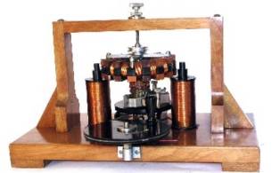
One of the examples of the early generator of the first stage is a generator from the laboratory of E. X. Lenz.
Near the poles of a permanent horseshoe-shaped magnet, five coils rotate, for the acceleration of rotation of which a gearing is provided from the large gear to the small one. The coils were rotated by hand. The windings of each coil were connected to the plates of the drum switch, through which the contacts slid. The switch was designed to supply a constant current to the circuit.
Magnetoelectric generator from the laboratory of E. X. Lenz
The need for greater effect of mechanical current generators led to the end of the first stage to the peculiar design of the company "Alliance", developed by Nolle (Belgium), van Malderen (France) and Holmes (England). This generator has 24 permanent magnets with eight radii of three in a row. At the poles of these magnets, 32 coils with a conductor passed, rotating. The current generated in the coils came to 32 collector plates, from which it was removed by means of rollers.
General view of the generator "Alliance": 1 - one of 24 horseshoe magnets, 2 - one of 36 rotating coils.
Further development of the generators along the line of increasing the number of magnets and coils became difficult, and the "Alliance" generator was the first stage machine. Generators "Alliance" were used to power the current of arc lanterns of lighthouses; In the years 1857-1865. About 100 such machines were in operation. One of them was set in motion by a steam engine with a capacity of about 10 liters. from.
The second period of the development of the generators, which lasted from 1851 to 1867, is characterized by the rejection of permanent magnets and the replacement of them by electromagnets, and a separate current source in the form of a first-stage magnetoelectric machine or in the form of a galvanic battery was used to power a current of electromagnets. An example of such a generator with independent excitation of electromagnets is the generator of the Englishman Wilde.
The generator consists of two independent generators, located one above the other and differing in that the upper small generator has permanent horseshoe magnets 1, and the lower one - electromagnets with a winding 2, fed by a current from the upper generator. Both are driven by belts from the engine.
Wilde's generator: 1 - permanent magnets; 2 - electromagnets.
Machines with independent excitation inevitably prepared the beginning of the third stage of development of generators. Indeed, when operating such machines it was easy to establish that the machine not only generates a current, being fed by the excitation current from its own coil, but because of the phenomenon of residual magnetism it makes it possible to generate a current from a state of rest. So there were electromechanical current generators with self-excitation, which became widespread since 1867.
The first patent for a machine with self-excitation was obtained by the Dane Chiort as early as 1854, but fearing that self-excitation would be insufficient, Hiort supplied permanent magnets in his generator. Therefore, the machine of Chiort, as a transitional type, did not attract due attention.
However, in 1866 the English engineers Cromwell and Samuel Varley, and at the beginning of 1867 on the same day the German Werner Siemens and the Englishman Whitston received patents for generators with independent excitement.
Now the question was only to find the most appropriate constructive forms in order to use the principle of self-excitation in the best, most effective way.
The decisive step in this matter was made by the French inventor, a Belgian by birth, Gramm in 1870-1871. Gram built a generator with self-excitation, giving the generator's armature the shape of a ring consisting of a bundle of wire. The windings of the electromagnets were fed by an armature current in series: the external circuit-collector-armature-collector-electromagnets-the external circuit. The annular anchor completely eliminated ripple currents, significantly increased the efficiency. And reduced the dimensions and weight of the generator by one unit of power.
One of the designs of the Gram generator with a ring armature: 1 - windings of electromagnets; 2 - pole tips covering the annular anchor 3; 4 - collector; 5 - current collector.
In the Gramm generator, the reversibility of the generator and motor regimes, established still by E.H. Lenz (1838), was quite clearly manifested in practice. Therefore, in the diagram, the line of the engine and the generator merge at the point corresponding to 1871.
Electric motors also had their own qualitatively different stages of development.
Ricci engine: 1, 2 - coils; 3 - mercury current-carrying switch.
The first stage of the development of an electric DC motor (1831-1834) originates from the experience of Faraday, who discovered the phenomena of mutual rotation of magnets and electric currents. If through a system consisting of a cup with mercury 1, a conductor 8-7-9, a second cup with mercury 2 with a conductor output at point 6, letting electric current flow from the galvanic battery, then the magnet 3 and conductor 9 will receive a rotational motion under the action of current.
This experience began the first stage, characterized by the design of physical instruments, showing the process of converting electrical energy into mechanical work.
At the second stage, the electric motor goes beyond the walls of the scientific laboratory. This stage is characterized by the practical direction of designers-inventors (1834-1860), providing for the replacement of the steam engine - the universal engine of the XIX century. - the electric motor.
For the second stage, the work of BS Jacobi, who designed in 1834 the first sample of his electric engine, is indicative. The U-shaped electromagnets of this engine were located in two groups: one group is fixedly fixed, the other can rotate. The electromagnets of both groups were supplied with a current from the galvanic battery in such a way that the polarity of the electromagnets changed, creating attractive or repulsive forces that led to the rotation of a group of mobile electromagnets.
Of the electric motors that were practically used in the 50's and 60's of the XIX century, it should be noted the engine of the French engineer Froman, used to drive typographic machines. The electromagnets of this engine are arranged in a circle (six pairs, in the figure, the upper two pairs are removed in order to better show the anchor of the engine with iron plates attracted and repelled by the electromagnets).
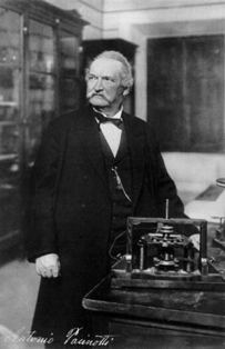
Electric motor Pachinotti
The second period ended with the creation of the engine by the Italian professor Pacinotti, who, ten years before Gramm, in 1860, constructed a circular anchor. The anchor rotated around the vertical axis between the pole pieces of the two electromagnets. The anchor and the electromagnets were supplied with a current in series, as in the Gram generator.
The only difference was that in the Gramm machine the annular anchor rotated in the plane of the electromagnets, and in the Pacinotti machine - in a plane perpendicular to the plane of the electromagnets. Characteristic is the fact that Pacinotti indicated that his engine can operate in generator mode, ie, being driven into rotation, it will produce an electric current.
Thus, in the diagram, the line of development of the generators coincided with the line of development of the engines on a DC machine with self-excitation and a ring armature, capable of operating as an engine and as a current generator.
P. S. Kudryavtsev. History of physics

Comments
When commenting on, remember that the content and tone of your message can hurt the feelings of real people, show respect and tolerance to your interlocutors even if you do not share their opinion, your behavior in the conditions of freedom of expression and anonymity provided by the Internet, changes Not only virtual, but also the real world. All comments are hidden from the index, spam is controlled.