
THE EXPERIENCE OF THE ELECTRIC ENERGY DISCOVERY
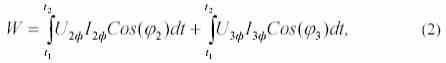
Accounting for electricity is an integral part of any enterprise. First of all, it is necessary for making money payments between the power supply organization and consumers. The main purpose of commercial electricity metering is to obtain reliable information on the amount of electricity consumed (issued). In three-phase four-wire systems, three-element electricity meters are used to measure the consumed electricity, which is a measuring wattmeter system and belong to integrating devices. The electricity meter is a device that reacts not only to the energy value, but also to the direction of its transmission, so when connecting the meter it is necessary to provide both correct currents directions and their correct combinations with the voltages in each counter element. The active energy measured by the counter in time t 2 - t 1 , is defined as:

Where the index "ф" denotes the phase voltages and currents. Let us determine the amount of underrecipitation of electric power for some of the most common faults in the elements of the metering system of electricity metering and errors in connection of electricity meters.
Breakage of the current circuit or secondary winding of the current transformer (CT). The current in the secondary circuit is zero, assume in the phase indicated by the index "1" (I 1ф = 0). With a symmetrical load, the active energy measured by the meter, according to (1):
those. Will be 2/3 of the actual value. The same amount of undercount is observed in the absence of voltage on one of the counter elements (on the parallel winding of the meter). The marking in the current circuits is interchanged, as a result of which the wires coming from the TT are exchanged, let's say the phases with the index "2". In this case, the current flows in all phases, but in the "2" phase it has the opposite direction. In other words, on the vector diagram (Figure 1) the current of phase "2" is rotated by 180 0 , therefore, the energy taken into account by the counter:
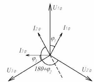
Figure 1. Vector diagram of currents and voltages on the meter when connecting the TT phase "2" with reverse polarity with active-inductive load.
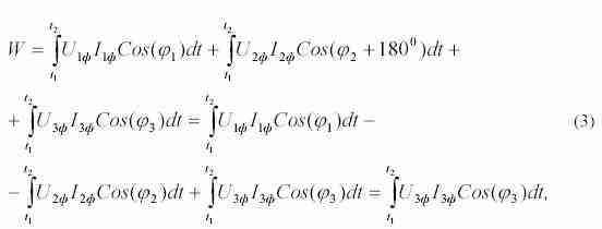
those. With a symmetrical load is 1/3 of the actual value.
To verify the correct connection of the counter, it is enough to take off the vector diagram and build it, compare it with the expected one, which depends on the nature of the load. Vector diagrams are most conveniently removed with VAF-85M or WAF-A instruments. In order to obtain a reliable measurement result, the vector diagram must be taken directly from the counter terminals, which are usually under the seal of the power supply organization, so you can use a simplified verification method, which requires: measuring all phase voltages and currents passing through the primary CT windings of all phases, Determine the total power by the formula:
![]()
- measure the number of revolutions of the active energy meter disk or the number of pulses of the light indicator (for electronic or microprocessor counters) N during the time T (30-60 seconds is enough), then determine the active power according to the formula:
![]()
Where К ТТ - CT transformation ratio; N is the gear ratio of the counter. If there is a reactive energy counter, measure the reactive power Q and calculate it using a formula similar to (5), and also determine the total power "by counters"
![]()
- compare the values of the total powers determined by formulas (4) and (6), which must coincide with the correct connection of the meter and the functional elements of the electricity metering complex. In the absence of a reactive energy counter, the values of S and P are compared, which, if the meter is correctly connected, should not differ from each other by more than Cos ( f ) times. The smallest error introduced by changing the load is achieved by "simultaneous" measurement of the phase currents and the rotational speed of the electric meter disk. With the help of the proposed simple measurements and calculations, it is possible to draw a conclusion about the correct connection of the electricity meter and the serviceability of the electricity metering complex (current transformers, measuring circuits from the CT to the meter, the parallel winding of the meter, voltage circuits) and the amount of undercounted electric power.

Comments
When commenting on, remember that the content and tone of your message can hurt the feelings of real people, show respect and tolerance to your interlocutors even if you do not share their opinion, your behavior in the conditions of freedom of expression and anonymity provided by the Internet, changes Not only virtual, but also the real world. All comments are hidden from the index, spam is controlled.