
Interface "Phoenix"
Interface "Phoenix"
In order to be able to communicate with the SIM card, you need a device that matches the PC and SIM card. The most common, yet simple enough and reliable is "Phoenix". There are several of its implementations, but they are basically identical. Differences consist only in how complicated the scheme of the "hardware" is. This affects the stability of the work, but even the simplest assemblies allow you to transfer and receive data normally.
I made my first "Phoenix" a long time ago (several years ago), tried other implementations of it and stopped at one of the schemes that has been working steadily for a long time.
Characteristic
Frequency of data transmission: 3.57 MHz;
Reset card: direct;
Connection: Com Port;
Power: external or Com Port;
Purpose: to communicate with SIM cards.
Assembly
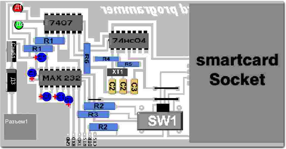
I propose to collect a scheme that combines "Phoenix" and "Ludipipo". The first one you already know, but the second one is a PIC microcontroller programmer. This combination is successful, if only because you do not need two devices for your experiments, you do not need to change the programmer to the reader (or vice versa), depending on the situation. Despite the fact that the circuit combines two devices, its complexity is not great.
You will need a sheet of foil-shaped textolite with a thickness of 1 - 1.5 mm, soldering accessories, ferric chloride (III), and details:
| amount | |||
All parts solder on the board according to the scheme:
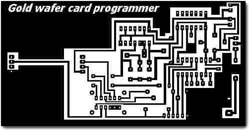
All the schemes can be downloaded in the form of this archive .

Comments
When commenting on, remember that the content and tone of your message can hurt the feelings of real people, show respect and tolerance to your interlocutors even if you do not share their opinion, your behavior in the conditions of freedom of expression and anonymity provided by the Internet, changes Not only virtual, but also the real world. All comments are hidden from the index, spam is controlled.