6. Analysis of the electrical diagram of the electrical installation
At present, specialists in our country are actively working to increase the level of electrical safety in electrical installations of residential and public buildings. The most important aspect of this work is the improvement and streamlining of the requirements of normative documents, especially in the field of standardization of the installation of electrical installations.
In order to expand the scope of electrical equipment of protection class I for electrical safety and taking into account the decision "On the development of the regulatory framework for the safe use of electrical equipment of protection class I for electrical safety in electrical installations of buildings" approved by Gosstroy of Russia, Gosstandart of Russia and the Ministry of Fuel and Energy of Russia (09.08.93) Electric power industry and Glavgosenergonadzor of the Ministry of Fuel and Energy of Russia decided to amend Ch. 7.1 Rules for the installation of electrical installations (PUE, 6 th ed., 1986) "Electrical equipment for residential and public buildings."
Paragraph 2 of this decision stated:
Enter an additional paragraph in clause 7.1.33:
"In residential and public buildings, the lines of the group network, laid from group panels to plug sockets, must be made with three-wire (phase, zero working and zero protective conductors) .The supply of stationary single-phase electrical receivers should be carried out by three-wire lines, with zero working and zero protective conductors Should be connected to the shield under a single contact clamp. "
Thus, the first step was taken to introduce TN-CS grounding systems in Russia for electrical installations of residential and public buildings.
In the PUE of the 7th edition, the requirements for the implementation of group networks are formulated as follows (paragraphs 7.1.36, 7.1.45):
7.1.36. In all buildings, the lines of the group network, laid from group, floor and apartment flaps to general lighting fixtures, plug sockets and stationary electrical receivers, must be made with three-wire (phase L, zero work N, and zero protective PE conductors).
It is not allowed to combine zero working and zero protective conductors of different group lines.
Zero work and zero protective conductors must not be connected to a common terminal.
Conductor cross-sections must meet the requirements of 7.1.45.
7.1.45. The selection of the conductor cross-section should be carried out in accordance with the requirements of the relevant chapters of the SAE.
Single-phase two- and three-wire lines, as well as three-phase four- and five-wire lines when feeding single-phase loads, should have a cross section of zero N working conductors equal to the cross-section of the phase conductors.
Three-phase four- and five-wire lines with three-phase balanced loads must have a cross section of zero N working conductors equal to the cross-section of the phase conductors, if the phase conductors have a cross section of up to 16 mm 2 in copper and 25 mm 2 in aluminum, and at large cross sections not less than 50 % Of the section of phase conductors, but not less than 16 mm 2 for copper and 25 mm 2 for aluminum.
The cross-section of PE conductors should be not less than the cross section of N conductors and not less than 10 mm 2 for copper and 16 mm 2 for aluminum, regardless of the section of the phase conductors.
The cross section PE of the conductors should equal the cross-section of the phase conductors with a cross section of up to 16 mm 2 , 16 mm 2 with a cross-section of phase conductors from 16 to 35 mm 2 and 50% of the cross-section of phase conductors with larger cross sections.
The cross section PE of conductors not included in the cable should be not less than 2.5 mm 2 - in the presence of mechanical protection and 4 mm 2 - in its absence.
In January 1995, a set of standards GOST R 50571 "Electrical installations of buildings" was developed, developed on the basis of the standards of the International Electrotechnical Commission. This set of standards contains requirements for the design, installation, adjustment and testing of electrical installations, the selection of electrical equipment.
One of the significant differences between the GOST R 50571 complex and the earlier existing standards is the classification of grounding systems.
Classification of grounding systems is presented in clause 312.2 of GOST R 50571.2-94. The grounding system is a general characteristic of the power supply network and the electrical installation of the building.
In the new edition of the PUE of 2001, the new requirements will be included in the final wording.
The following earthing systems exist: TN-C, TN-S, TN-C-S, TT, IT (Fig. 6.1-6.5).
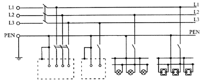
Fig. 6.1. TN-C System
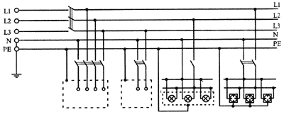
Fig. 6.2. TN-S system
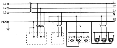
Fig. 6.3. TN-CS System
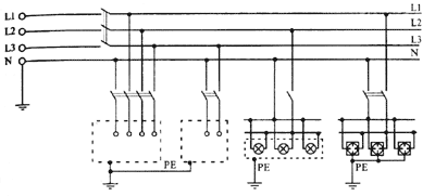
Fig. 6.4. TT system
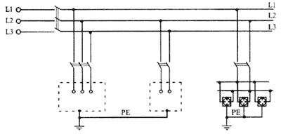
Fig. 6.5. IT system
The first letter in the designation of the grounding system determines the nature of the grounding of the power source:
T - direct connection of the neutral of the power source to the ground;
I - all current-carrying parts are isolated from the ground.
The second letter determines the nature of the grounding of the open conductive parts of the electrical installation of the building:
T - direct connection of the open conductive parts of the electrical installation of the building to the ground, regardless of the nature of the connection of the power source to the ground;
N - direct connection of the open conductive parts of the electrical installation of the building with the ground point of the power source.
The letters following the dash for N determine the nature of this connection - the functional method of constructing a zero protective and zero working conductors:
S - the functions of the zero protective PE and the zero working N conductors are provided by separate conductors;
C - the functions of the zero protective and zero working conductors are provided by a single common conductor PEN.
In Russia, to this day, a system similar to TN-C (Figure 6.1) is used in which the open conductive parts of the electrical installation (enclosures, electrical equipment enclosures) are connected to the grounded source neutral by a combined zero protective and working conductor PEN, i.e. Are "nullified". This system is relatively simple and cheap. However, it does not provide the necessary level of electrical safety.
The systems TN-S (Figure 6.2) and TN-C-S (Figure 6.3) are widely used in European countries - Germany, Austria, France, etc. In the TN-S system, all open conductive parts of the building electrical installation are connected by a separate zero protective Conductor PE directly to the grounding device of the power supply.
When installing electrical installations, the regulations prescribe a wire with a yellow-green insulation marking for the PE protective conductor.
In the TN-C-S system (Figure 6.3) in the input device of the electrical installation, the combined zero protective and working conductor PEN is divided into a zero protective PE and a null working N conductors.
In the TN-C-S system, the neutral protective conductor PE is connected to all exposed conductive parts and can be repeatedly grounded, while the working conductor N must not have a ground connection.
The most promising for our country is the TN-S-S system, which, in combination with the widespread introduction of RCDs, ensures a high level of electrical safety in electrical installations without their radical reconstruction.
Important note!
In electrical installations with TN-S and TN-S-S earthing systems, the consumer's electrical safety is ensured not by the systems themselves, but by residual current devices (RCDs) that operate more efficiently in combination with these grounding systems and a potential equalization system.
Actually the grounding systems themselves - without an RCD, do not provide the necessary safety. For example, in case of breakdown of insulation on the body of an electrical appliance or any apparatus, in the absence of an RCD, this consumer is disconnected from the network by means of overcurrent protection devices, either automatic switches or fuse-links.
The speed of protection devices against overcurrents, firstly, is inferior to the speed of the RCD, and, secondly, depends on many factors - the multiplicity of the short-circuit current, which in turn depends on the resistance of the conductors, the transient resistance at the fault location of the insulation, the length of the lines, the accuracy Calibration of circuit breakers, etc.
The presence of metal enclosures, fittings, etc., connected to a PE conductor, increases the danger of electroporation, because in this case the probability of forming a chain: "conductor conductor - human body - earth" is much higher. Only the RCD protects against direct contact.
The introduction of TN-S and TN-C-S systems in European countries, to the experience of which we have to constantly consult, because there the problems under consideration were solved two decades earlier, also took place with great difficulties. For example, in the literature, a case is described when an electrician, when connecting one object, incorrectly connected the phase to a protective conductor, which resulted in the death of several people.
In terms of ensuring electrical safety in the operation of the electrical installation, a relatively new but increasingly widely used effective electrical protective device, a double insulation, is a serious alternative to the above grounding systems.
The achievements of the chemical industry in the field of the production of plastics and ceramics having excellent mechanical and electrical insulating characteristics have made it possible to significantly expand the range of electrically safe electrical appliances and power tools in the "double insulation" version, in which the type of grounding system does not matter in terms of ensuring electrical safety conditions.


Comments
When commenting on, remember that the content and tone of your message can hurt the feelings of real people, show respect and tolerance to your interlocutors even if you do not share their opinion, your behavior in the conditions of freedom of expression and anonymity provided by the Internet, changes Not only virtual, but also the real world. All comments are hidden from the index, spam is controlled.