9.14 switching circuits RCD
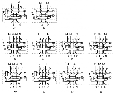
Construction RCD from different manufacturers may differ from each other only by parameters and connection diagrams. Fig. 9.1 are the most common strategies to incorporate RCD. In addition, the inclusion of RCD shown in one-, two- and three-phase versions.

Figure 9.1. RCD Wiring Diagrams:
a, b - pole RCD; c, d, e, f - four-pole RCD, which resistor to simulate a differential current, is connected to the phase voltage; g, h, and, - on the line voltage.
When the RCD variant for unbalance is necessary to pay attention to the correct connection of the conductors to the terminals of the device - must be connected resistor circuit testing. Wiring is shown on the front or side surface of the RCD body.

