
The effect of pulse-width modulation on the error of induction energy meters and on losses in an asynchronous motor
Effect of pulse width modulation For error Induction electricity meters and losses in asynchronous The engine
AP Popov, AO Chugulev, AA Gorshenkov, SM Klevanskii
Siberian State Automobile and Highway Academy (SibADI)
The results of a study of the error of induction counters of electric energy as well as electric losses in an asynchronous motor under conditions of a high level of harmonics in current and voltage curves are presented using the Mitsubishi frequency inverter ( E 500 FR - E 540-5.5 K - EC ) in As a source of nonsinusoidal voltage. It is shown that the error of induction electricity meters and electric losses in an asynchronous motor with non-sinusoidal regimes in circuits with PWM increase by several tens of percent.
As is known, in power supply systems in connection with the increase in electricity consumers operating in the pulsed mode, as well as systems with pulse-width modulation (PWM), frequency converters in electric drive systems with asynchronous motors, nonlinear loads, thyristor converters, etc. A high level of higher harmonics arises.
In this regard, the issue of measuring electrical energy in these conditions remains relevant, in spite of the fact that a significant amount of work has been devoted to the measurement of electrical energy, both under sinusoidal regimes and under conditions of non-sinusoidal electromagnetic processes, for example [1: 6] .
To measure electricity in power supply systems, both induction and electronic electricity meters are currently used. Moreover, the latter are most often based on analog-digital converters using microprocessor calculators, that is, in the process of calculating the electric power, the time measurement is quantized and the input signals proportional to the current values of the current and voltage on the load are quantized, which inevitably generates an error in calculating the energy.
In this paper we present the results of an investigation of the error of induction counters of electric energy, as well as power losses in an asynchronous motor under conditions of a high level of harmonics in the current and voltage curves. At the same time, a special electronic electric energy meter was used, which allows obtaining reliable information in conditions of non-sinusoidality caused by PWM.
As such an electronic counter, a specially designed electronic counter has been used for this purpose, which provides with a high enough accuracy the calculation of the current value of electricity
![]() In comparison with the induction counter, in accordance with the expression:
In comparison with the induction counter, in accordance with the expression:
 , (1)
, (1)
Where
![]() - Instantaneous voltage on the load;
- Instantaneous voltage on the load;
![]() - instantaneous value of the load current;
- instantaneous value of the load current;
![]() - current measurement time.
- current measurement time.
In the structural scheme of such a counter as a multiplier of instantaneous values
![]() and
and
![]() A pulse multiplier, a pulse integrator and a digital pulse counter are used, which makes it possible to provide a total error in measuring the current electric power of the order of several tenths of a percent (0.1¸0.2%) under conditions of a high level of higher harmonics at frequencies of a multiple of 50 Hz, Frequencies of several tens of kilohertz, and use it as an exemplary means of measuring electrical energy.
A pulse multiplier, a pulse integrator and a digital pulse counter are used, which makes it possible to provide a total error in measuring the current electric power of the order of several tenths of a percent (0.1¸0.2%) under conditions of a high level of higher harmonics at frequencies of a multiple of 50 Hz, Frequencies of several tens of kilohertz, and use it as an exemplary means of measuring electrical energy.
This paper does not attempt to describe the complete structural and principal electrical circuits of such a meter (such information can be provided to interested organizations and institutions). One of the tasks is to determine the possible level of induction meter error in non-sinusoidal modes with a high level of distortion of the current and voltage curves on the load.
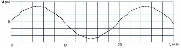
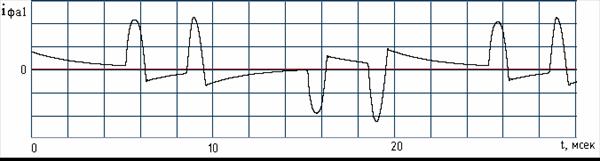
The studies were carried out using a frequency converter (PE) Mitsubishi E 500 FR - E 540-5.5 K - EC with a nominal power of 5.5 kW. As a load, heating elements and an asynchronous motor were used. The block diagram of the installation with the heating elements and the time diagrams of the currents and voltages are shown in Fig. 1 and Fig. 2 .
Fig. 1. Structure of the installation: Wh 1, Wh 3 - induction electricity meters CO 505; Wh 2, Wh 4 - electronic electricity meters; TT - current transformer; ДН - the gauge of pressure; PE - frequency converter; R n is the load resistance.
Before the experiment under non-sinusoidal conditions, a preliminary check was made to identify the readings of the electronic and inductive counters when operating for the same load in a mode close to the sinusoidal. The diagram of switching on the devices is shown in Fig. 3. The time diagram of the stress curve on the load is shown in Fig. 2a .
B)
at)
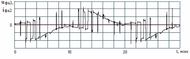
Fig. 2. Time diagrams of phase voltages (a and c) and phase currents (b and c)
At the input and output of the emergency for the case of a linear active load

Fig. 3. Scheme of checking induction and electronic counters on
Identification of readings in the mode close to sinusoidal
During the experiment, the following operating mode of the frequency converter was used:
- Frequency of the fundamental harmonic of the voltage at the output of the FP is f = 50 Hz;
- frequency of PWM voltage at the output of the emergency - 1 kHz;
- load resistance of the frequency converter R H = 38 Ohm (close to the nominal mode)
Several experiments were carried out with a fairly accurate measurement of the operating time of the electricity meters and recording their readings.
According to the indications of electronic energy meters, the average value of the efficiency of the frequency converter is determined at the specified load:

Where
![]() - average value of output power;
- average value of output power;
![]() - average value of power consumption;
- average value of power consumption;
(The standard deviation of the readings from the mean was 0.05%)
As a result of the measurements performed according to the scheme in Fig.
1 , relative values were set
![]() Differences in indications of electronic and inductive electricity meters in percents on input and output of emergency, which, taking into account statistical processing, were as follows:
Differences in indications of electronic and inductive electricity meters in percents on input and output of emergency, which, taking into account statistical processing, were as follows:
![]() ,
,
![]() .
.
From the results obtained, it follows that for the same load values under conditions of non-sinusoidal modes in PWM circuits, the basic error of induction counters is several tens of times greater than their basic error with a sinusoidal mode.
The results of the study are obtained, as already mentioned, for a linear active load. Due to the fact that PE is used mainly to supply asynchronous motors (AD) for the purpose of regulating the speed, an experiment was conducted to determine the power losses in the AD when powered by a Mitsubishi E 500 FR - E 540-5.5 K - EC . For the experimental studies, the asynchronous motor AIR100 L 2 Y 3 (rated power 5.5 kW, 3000 rpm) was used. As the load of the AD, a generator of direct current with mixed excitation loaded onto the heater is used. Preliminary measurements were made of the power of the BP consumed and the load in the sinusoidal mode. After processing the experimental data, it was found that, when the blood pressure is supplied from BP, all other things being equal, the power losses in blood pressure increase by 30% as compared with the sinusoidal regimen. This leads to a change in the thermal regime of blood pressure and the need to reduce its load. The reasons for the increase in losses in blood pressure under non-sinusoidal regimens are known and are not discussed in this paper. The main goal was to establish the level of these losses.
Conclusions:
1. For the first time, the level of the basic error (tens of percent) of the induction counters of electric energy in the non-sinusoidal conditions created by PWM has been experimentally established.
2. Losses in regulated asynchronous motors, powered by PE, also increase by several tens of percent compared to the standard power mode, which leads to overheating of the AD and the need to reduce the load power.

Comments
When commenting on, remember that the content and tone of your message can hurt the feelings of real people, show respect and tolerance to your interlocutors even if you do not share their opinion, your behavior in the conditions of freedom of expression and anonymity provided by the Internet, changes Not only virtual, but also the real world. All comments are hidden from the index, spam is controlled.