
|
Start of section
Production, amateur Radio amateurs Aircraft model, rocket-model Useful, entertaining |
Stealth Master
Electronics Physics Technologies Inventions |
Secrets of the cosmos
Secrets of the Earth Secrets of the Ocean Tricks Map of section |
  |
| Use of the site materials is allowed subject to the link (for websites - hyperlinks) | |||
Navigation: => |
To main |
|
INJECTOR ECOTOP
![]()
Dudyshev Valery Dmitrievich, Russia, Samara
Samara Technical University
See also: |
For today it is possible to calculate that in Russia the transition from carburetor power systems of internal combustion engine to injection or external injected mixture of engines with forced ignition is carried out. The basis for this approval is the fact that all the prospective AvtoVAZ models (VAZ-2110, VAZ-2114, VAZ-2115) are now equipped with engines with fuel injection system.
In all these engines, injection is carried out in the engine intake manifold ( external mixture formation ). In this case, because of the lack of a carburetor, the reaction of the intake system decreases (part of the pumping losses), the uniformity of the distribution and the accuracy of the fuel dosage along the cylinders increase and it becomes possible, depending on the regime, to more flexibly control the law of the fuel-air mixture entering the engine cylinders . This makes it possible to increase the compression ratio, but therefore, the liter capacity and economy of the engine . But in time the increased fuel supply in transient modes and with engine warming leads to increased toxicity of exhaust gases in similar modes, the need for additional purification of primary exhaust gases begins. The peculiarity of the work of external mixture formation systems based on distributed injection leads to undesirable uneven distribution of fuel vapors over the combustion chamber capacity (a small time for the formation and mixing of the fuel charge), the negative consequences of this affect certain regimes, let us assume the regime of XX and imposing loads.
It should be noted that partial load regimes, such an uneven distribution of fuel plays a certain positive role. To maintain the possibility of sustainable work, it is necessary to apply increased spark plug gaps and increased power of the electric discharge.
The engines of the above- mentioned VAZ cars are VAZ-2112 (sixteen-valve) and VAZ-2111 (eight-valve) motors, of which the most widespread has so far received a final one. Both engines have a distributed injection, i.e. For each cylinder, fuel is injected by a separate injector. There are distributed injection systems with and without feedback. The first so far is mainly used on the export VAZ-2110 . In them, a neutralizer and an oxygen sensor are installed in the exhaust system, which provides feedback. The sensor monitors the concentration of oxygen in the exhaust gases, but the controller (microcomputer of the electronic control system ICE ), according to its program and signals from other sensors, maintains an atmosphere-fuel ratio that ensures the most efficient operation of the neutralizer.
However, it must be taken into account that the reverse union and oxygen regulation (lambda probe) is possible only with the ICE work on the stoichiometric composition of the fuel mixture, of course, and the three-component catalyst is designed to work with such a mixture composition, therefore, the possibility of labor in an economical mode, In power, too. We have to move to various kinds of complications to bypass the rectilinear automatics and ecology in favor of power. Special conditions appear in the cold start and up to warm-up mode (fuel is supplied several times more than for the warmed-up ICE ), but there are no conditions for its evaporation, so the toxicity of the exhaust increases sharply.
In the system of injection without feedback, the neutralizer and oxygen sensor are not installed in any way, but for the purpose of adjusting the CO concentration in the exhaust gases, there is a CO- potentiometer that is used once at service stations when adjusting the CO content in the exhaust of the car at idle.
The question arises: Why do I need a neutralizer and an oxygen sensor with an injection? But here is not all as simple as if I would like. At the main eye, the ecological characteristics of the ICE with injection should definitely be higher than that of the carburettor: the fuel is supplied in a strict, optimal ratio with air at the most favorable time, etc. But this is characteristic for the sake of the established regime. In the transitional mode of power dialing, this ratio is not observed in any way, due to the priority of the gas pedal signal, therefore, the command to the controller is received for the sake of increasing the fuel supply, the fuel supply to the injector is sharply increased (before the cutoff by the oxygen sensor signal, but it moves after in time) and Limited air intake, due to the inertia of the process and not yet increased turnover of ICE . Moreover, the system can supply very impressive portions of fuel in transient modes and maximum load, so the oxygen sensor and neutralizer limit possible harmful emissions, respectively, and maintains a given economy and toxicity.
Indeed, this is so, but often we do not think how the fuel is actually supplied. In the carburetor, the fuel is sprayed by the pneumatic principle - the high-speed flow of the atmosphere and the diameter of the droplets that form as a result of it reaches 20 μm in the main driving modes of the car. Sharply worsens the carburettor spraying on cold engine startup modes, and partly sharp acceleration.
In injection systems, fuel is sprayed through the nozzles due to pressure in the feeding system (mechanical spraying). The pressure in the fuel stage of the VAZ-2111 engine is relatively low - it achieves 284 KPA (about 3 atmospheres). In this case, the nozzles create droplets with a diameter of about 50 μm . Larger droplets evaporate worse and therefore mix with air less. This leads to the formation of local, fuel-enriched zones, which in turn are the centers of formation of CO and CH , etc. An additional negative factor is that due to a much smaller route through the intake system, the fuel drops do not have time to evaporate and mix with the air. The role is also played by the fact that after closing the intake valve, the air column (the fuel mixture in the case of the carburetor) continues to run, the so-called aftercharging occurs at the subsequent moment of opening the intake valve. Therefore, the mix is still slightly heated from the walls and the valve. When injected, the possibility of heating and evaporation of droplets remains only from contact with an already open or opening valve (and this time is extremely short) and therefore the quality of atomizing the fuel with the injector becomes paramount. But since the operating regimes of each injector are extremely wide (from very small doses to the XX , up to the maximum at full power), it is extremely difficult to ensure a high-quality fuel atomization. Imposes an imprint and labor with impressive engine speed, where there is quite a clear limit on the efficiency of the injectors due to inertia of the parts and the impossibility of high-quality spraying of fuel, but it seems that the change is temporary because of the low quality of the fuel, which worsens the parameters of the injectors. There is a need to increase the operating pressure of the injectors (rather expensive measure) and to take special measures, including the variable length of the intake duct (new ZMZ engines ) and considerable multiplication of the spark gap of the spark plug and the power of the electric row (all injector ICEs ). So, it appears that on driving modes the carburetor by virtue of its system is not inferior to the engine with injection, but the bowl exceeds it in the quality of fuel spraying (though only in those cases when it is working and correctly adjusted). Checking the technical condition of the car and measuring the level of toxicity of exhaust gases are carried out, as if the position, on standing cars, in which place the carburetor is inferior in terms of environmental parameters to the injection systems. At the same time, in developed countries, the measurement of environmental characteristics for the sake of cars is trying to be carried out for the driving cycle and at the time the situation is radically changing. That's why on export cars there are a neutralizer, oxygen sensor and feedback.
All of the above indicates that the injection systems need to improve the mixture, which would allow to abandon the expensive neutralizer, which also needs to be replaced at certain intervals of the pore and is extremely critical to the quality of fuel.
First we will consider, as if the mixture formation in the engine with injection on the DVS VAZ-2111 engine results . Electric rotary pump type, standing in the gas tank, provides fuel supply under pressure of 284 KPa . Through the fuel filter, the fuel enters the injector frame, which is a hollow bar with injectors installed on it and a fuel pressure regulator. The nozzles with their diffusers go into the openings of the inlet pipe (collector). The injector is a solenoid valve, which is opened at the command of the controller. At the same time, the fuel is injected at an angle into the inlet pipe by the inlet valve through the atomizer. Here, the fuel partially evaporates, coming in contact with the heated parts, and in approximately vaporous state it caters to the combustion chamber mixing with the incoming air along the path. After stopping the electric pulse, the spring-loaded injector valve closes the fuel supply. The fuel pressure regulator ensures a constant pressure drop between the intake pipe and the fuel rail.
The quality of the mixture formation largely determines the combustion process of the fuel-air mixture. From the point of view of the mixture formation, for combustion purposes, a pair of limiting cases are distinguished: a diffusion flame and a flame in a fuel- air mixture ( FA ). In the main case, the fuel and atmosphere are mixed directly in the flame zone by the diffusion route, in the other - up to the burning. Numerous studies have shown that in the main case, the generation of harmful substances ( CO , CH and NOx ) during combustion will be higher. Imagine this can be as follows. Diffusion combustion is more typical for large drops of fuel, which on the route to the combustion chamber can not completely evaporate and merge with air in a qualitative way. As a result, local diffusion combustion is realized in the combustion chamber of the internal combustion engine , the course of which is limited in time, because The burning process in the internal combustion engine is periodic. The consequence of this will be a fuel burn-out and an increased content of CO and CH in combustion products. The pre-prepared mishmash is characterized by a more even distribution of fuel vapors through the atmosphere, the combustion in this case does not result from the surface of the drops, as if in the previously discussed case, but throughout the fuel assembly , leaking more quickly (the burning rate depends on the overall fuel / air ratio ). And in some cases (modes), the most effective combustion is possible with the task of stratifying the fuel charge, in which the charge consists of layers of a fuel-air mixture and a clean atmosphere or waste gases (during recycling), since in these cases the overall combustion temperature decreases and, therefore, the possibility of oxides Nitrogen ( NOx ).
Therefore, in DVS it is necessary to strive for the qualitative preparation of fuel assemblies, for which in the engine with injection it is necessary to achieve the following:
- It is necessary to acquire smaller droplets of fuel, for which it is necessary to additionally crush the droplets created by the injectors.
- It is necessary to provide a better mix of evaporated fuel and its droplets with air.
- To create a uniform distribution of fuel through the air flow, to exclude the rearing of zones with an enriched fuel mixture.
- Produce a proportional and balanced stratification of the fuel charge with the atmosphere or waste gases.
At the same time, the task begins - for the sake of which to improve the mixture formation, if the modern ICE with injection approximates our ecological norms. (Note: Norms of Euro 3 and 4 conventional injection gasoline internal combustion engines without a significant change in the system does not pass, not to mention the normalized portion of carbon dioxide, the actual fuel consumption of 3-4 liters per 100 km ). Indeed, the norms are fulfilled, but literary sources forget to tell what price. The lesson is that the exhaust system of every car owns hydraulic resistance. This is due to the system of the exhaust system, which is a set of expanding areas in which are installed perforated plates or grilles, due to the passage of which the exhaust gases lose their speed and temperature, but as a result acquire other acoustic characteristics, issuing less sharp sounds at the exit of the exhaust pipe. At the same time, such a system hinders the free exit of exhaust gases, which in turn slightly reduces the filling ratio of the cylinder of fresh fuel assemblies, but this reduces the power. Therefore, sports cars use silencers to another system, where the sacrificing of sound characteristics increases the power. Installation in the exhaust system of the neutralizer leads to an additional increase in resistance at the outlet, but it means even more power reduction. It was this that led to the appearance of the expression "crushed by the neutralizer" as applied to engines equipped with them. True, many owners of the " dozen " notice that the VAZ-2112 engines with the neutralizer have worse dynamic characteristics. Partly can solve the problem of turbocharging. But this complication and the rise in price of the engine . Such is the reward for the environment.
We recommend another route, the meaning of which well reflects the poster, previously hung on the walls of many institutions: "It's not exactly where they're going, but where they do not litter in any place." Indeed, why compete with emissions, at what time they are, at what time can one at once make a dump that they did not exist at all.
Let's return to our four points. The necessity of the principal, connected with the diameter of the droplets is justified in the source of the article, but why the following three? The lesson is that every engine works at a certain ratio of fuel to air, which corresponds to the known coefficient of excess of the atmosphere, which for the gasoline ICE lies in the range of 0.8 ... 1.15 (ie, close to the stoichiometric composition of the mixture).
According to the experiments in the model installations for such a, neither CO nor CH common in any way should be formed when burning homogeneous fuel assemblies. Yet everyone knows that this is not the case with the ICE . Why? Yes, because in the class itself, the size 0.8 ... 1.15 does not in any way characterize the actual ratio of fuel to atmosphere in all zones according to the capacity of the combustion chamber. It is calculated on the basis of the number of fuels and atmospheres received in the engine , not taking into account their further distribution, inter alia, as a result of insufficient mixing in the combustion chamber, there may be room and zones with c = 0.3 ; And c = 0.5 , etc. To reduce the number of such zones enriched by fuel, it is necessary to ensure a qualitative mixing of fuel with the atmosphere throughout the tank or to produce a proportional stratification of the fuel charge (without re-enrichment zones). In addition, the process is complicated by the fact that in different modes the alpha coefficient needs to be changed somewhat. To obtain maximum power from the ICE, a "power train" is required, at modes XX it is desirable to escape from the "power composition", partial depletion requires a depleted mishmash (economy), etc. This complicates the processes of fuel management and the quality of fuel charge education.
In order to work out measures that provide such contradictory requirements, let's try to figure out what prevents the qualitative mixing of fuel with the atmosphere in existing combustion engines with injection. The injector injects fuel into the intake manifold at an acute angle to the course of the air flow. At the same time, the fuel particles move approximately parallel to the associated flow of air, which seems to do nothing to promote their intensive mixing.
Multi-section spraying of the nozzle (for the case with duplicated inlet valves) does not seem to be distinguished by the intensity of mixing. As is known, qualitative mixing can be achieved in several ways: due to a significant increase in the speed of one of the components of the mixture, due to their collision or increase in the contact pore, and the collision alienates the greater effect. In the classical case, almost nothing is observed. Therefore, in order to improve the mixture formation, one of the methods must be used. Since it is by no means feasible to change the speed ratio by an unsophisticated route, the conclusion is that there is an additional flow of the atmosphere in a plane perpendicular to the fuel injection. Such additional vortex flow of the atmosphere will lead to further fragmentation of the fuel droplets, but it seems to improve the quality of the mixture formation. Moreover, it is possible to get the route of error-free configuration and organization of additional thin vortex jets and streams, as if crushing and intensification of mixing with air, and a balanced stratification of the fuel charge by the atmosphere or by exhaust gases (partial recirculation).
Earlier, a somewhat similar solution, however, for the sake of carburetor ICE , was offered by Professor AP Merkulov / 1 / who worked at the Samara State Aerospace University and created a vortex carburetor. AP Merkulov decided to use a vortex tube, which works on the Ranke effect as a carburettor and a fuel injector. The possibility of such use of the vortex tube was explained by its specific properties: the ability to create rarefactions in the vortex core with small pressure drops, intense mixing, the presence of zones of high and low temperature in the vortex, the occurrence of intense sound and ultrasonic vibrations and ionization in the vortex zone. The purpose of the vortex carburettor was to achieve a vaporized fuel already in the carburetor. This made it possible to eliminate the uneven composition of the mixture along the cylinders, dilution and flushing of the lubricant on the cylinder walls, drops of unused fuel, incompleteness of combustion and fuel overexpenditure. Various variants of the vortex carburetor have passed tests on automobile engines GAZ-21, GAZ-24 and VAZ-2106 . In their course, it was possible to establish that in addition to the expected effects with the use of a newly made carburetor, the requirements for the antiknock properties of fuel can be reduced, which made it possible to use cheaper fuel or to increase the compression ratio in the engine , hence its power and economy. The following results were obtained from the expected characteristics. On partial loads, compared to the standard carburetor, 15% fuel economy was provided by depleting the mixture and increasing the completeness of fuel combustion. At idling, the vortex carburetor reduced the specific fuel consumption by 25 ... 30% . High completeness of combustion ensured a 50 ... 70% reduction in the essence of CO in combustion products. Unfortunately, in the then conditions, the vortex carburetor could not be put into mass production. The vortex carburettors worked according to the following principle (see Fig. 1). Air from the atmosphere passed through the filter element and entered the vortex tube through the nozzle inlet. At the expense of rarefaction in the near-axis zone, the fuel that was injected into it from the float chamber through the nozzle was intensely sprayed and evaporated. Large unevaporated droplets were picked up by a whirlwind and sprayed to the wall of the vortex tube, where they fell into the zone of high temperature, and, evaporating, moved together with the peripheral vortex to the hot end of the vortex zone. It is necessary to note the following. Such education of a full-flow vortex can lead to undesirable effects, for example: either low efficiency in regimes XX , or excessive turbulence of the flow at elevated modes and failure of combustion, which will lead to a gap in the combustion cycle and unstable ICE work.
Despite this, this system indicates advantages that correspond to the twist of the atmosphere when fuel is sprayed, but it can not be used in any way without making significant changes to the engine system. The path of the intake pipeline does not allow to mount the vortex tube, of course, and the full-flow wind is not always practically desirable. Therefore, in our case it is more expedient to create a twist of the atmosphere in the nozzle zone without a vortex tube, and for the sake of creating a vortex use only a small fraction of the light flux.
Let's try to estimate at first, whether in this case there will be an effect from this. B / 2 / provides a formula for estimating the impact of a fuel jet on a rotating surface:
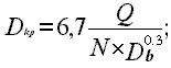
Where D kp is the medium Sauter diameter of the droplets (droplet diameter, in which the ratio of capacitance to surface area is equal to this value for the sake of the whole aerosol); N - speed of rotation, rpm ; Q - waste of liquid; ( m 3 / s ); D b is the rotation diameter of the vortex
For the VAZ-2111 engine, the diameter of the intake pipeline is 30 mm , so we take D b = 30 mm (Fig. 2). The fuel consumption will be equal to 7 liters / hour , which corresponds to 1.9 * 10-6 m3 / s . To calculate the rotation speed N, it is first necessary to calculate the circumferential air speed. For this we use the well-known formula:
![]()
Where in our case c is the circumferential air speed, p is the air density, but F is the area of the nozzles providing the atmospheric inlet to the pipeline. Since in the combustion engine the expenditure of the atmosphere is proportional to the expenditure of fuel, we use the formula:
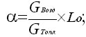
Taking for the sake of calculations a = 1 , L o = 15 . For the volumetric waste of fuel above, its mass waste becomes equal to the creation of volumetric waste for the density of gasoline (we assume 750 kg / m 3 ). Having expressed from the formula and having carried out its calculation, we get the value 0.021 kg / s . Further, it is necessary to determine the area over which air will be supplied. For this we use the formula / 1 / . According to it, the total area of the openings of the atmosphere is determined by the formula:
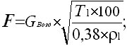
Here is the temperature of the atmosphere (we assume 293K); - its pressure in kg / cm 2 (in our case, atmospheric pressure). After the calculation, we obtain F = 94 mm 2 . This area corresponds to a circumferential velocity c = 196 m / s .
Now calculate the corresponding rotation frequency, using the formula c = NR and substitute it in the formula for the diameter of the drops. The calculation alienates the value of D32 = 4.9 * 10 -5 mm . It should be noted that the calculation was estimated. But it shows that even if the diameter of the vortex decreases (which the room will actually have), it will be possible to achieve a qualitative crushing of the drops. In reality, in any case, their diameter will be less than 50 μm , since in our case, the jet is not jetted but the droplets emanating from the nozzle. This indicates a significant effect from the collision of the spray cone of the nozzle with the swirling twist of the air.
There is a formula / 2 / for calculating the time necessary for the evaporation of a single drop:
Ti = k (air density) x with xD xD / 8xk2x (1 + B) (1 + 0.25Re to the power of 0.5
Here B is the mass transfer parameter, k is the reaction rate constant, D is the droplet diameter, r is the fuel density, and c is the heat capacity of the air.
Assuming all the quantities entering the equation unchanged when comparing the standard case and the case with the intensification of air swirling, we find that the time for evaporation is directly proportional to the square of the diameter of the drop. Assuming that when using the twist, it will decrease by a factor of two, we find that the required time for evaporation in this case will decrease by a factor of four.
Consequently, with intensification with a twist, the probability of a more filled vaporization of droplets is much higher. In work / 2 / is shown a graph of the dependence of the propagation velocity of the flame S on the droplet diameter and the fraction of the evaporated fuel (W) - see Fig.
It can be seen from this graph that multiplying the droplet diameter by a factor of about a factor reduces the flame propagation speed by the same amount. The decrease in the flame propagation speed in turn leads to the incompleteness of the combustion process for the time allocated for it in the ICE cycle and underburning of the fuel. Variations in the burning rate of the fuel mixture in different modes require the complication of the angle control system ahead of the ignition. Excessive reduction in the burning rate, in general, worsens the characteristics of ICE , including environmental ones.
From the foregoing, it is clear that the intensification of the process of spraying the fuel with the route of creating an intersection with the vortex twist of the atmosphere reduces the diameter of the fuel droplets, accelerates their evaporation, and ultimately increases the burning speed. Together, all of these factors should contribute significantly to improving the combustion process and reducing CO , CH and NOx emissions .
Further, it is necessary to solve the system of technical questions, so that the realization of the idea becomes almost feasible. So, for example, the question arises, how is it best to create a twist of air? Multiple experiments by Professor AP Merkulov showed that for this purpose it is most expedient to use a snail, the inner surface of which is made in the Archimedes spiral. It in turn can be performed with one and multi-nozzle inputs.
The next important task is where, in which room to carry the air supply.
Examination of the transverse section of the VAZ-2111 engine illustrates that fixing the spacer for the sake of supplying the atmosphere without making changes to the engine system can be carried out in the mounting room of the receiver to the intake pipe or in the mounting chamber of the intake pipeline to the cylinder block. In the main case, the atmosphere is supplied up to the fuel injection location, in the other after. Analysis of the spacer installation for the sake of both variants illustrates that in the main case only mixture formation will improve, since The speed of twisting of the atmosphere stream at the nozzle will already fall, but in the other case a full effect will appear, including additional ones, such as if proportional to the degree of stratification of the fuel charge.
The next important point, which limits the possibility of using the intensification of fuel sputtering by a vortex twist for the sake of an engine with injection, is the measurement of air flow. The lesson is that for the ICE with injection of the waste of the atmosphere is one of the main parameters by which the microprocessor generates commands for controlling the parameters of fuel injection. Therefore, the input atmosphere must be measured. There may be several solutions. First, the atmospheric supply to the vortex intensifier (spacer) can be carried out from the atmosphere through a single filter and an additional thermo-anemometer type meter installed behind it. In this case, the microprocessor of the injection system will have to take into account the signal, as if the main, and additional sensors, which may require changes in its design. Secondly, the selection of the atmosphere for the sake of spacer can be carried out from the room behind the air flow sensor. Third, the twist can be carried out for the sake of the entire flow of air entering the cylinder, just as if it were made on some types of diesel engines. In the case of a twist with additional recirculation of the exhaust gases, an amendment to the controller program is introduced, since the percentage of recirculation is usually small. Moreover, additional recirculation can only be used as a means of vortex stratification of charge, but a light wind for the intensification of the mixture formation. The plus of the other and the third methods is that additional sensors for the sake of measuring the waste will not be required, which will make it possible to dispense with the development of new software.
It should be noted that the general course of the vortex twist must be consistent with the location of the intake valve (s) in the combustion chamber.
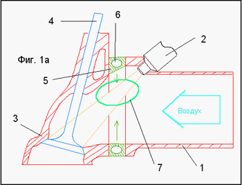
Schematic representation of the swirler installation room Fig. La.
1 - Intake manifold; 2 - Nozzle; 3 - Block head; 4 - The inlet valve; 5 - Swirl; 6 - Internal air cavity of the swirler; 7 - Vortex flow area.
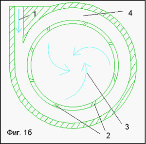
An approximate front view of the swirler flow Fig. 1b.
1 - Input air flow; 2 - Inclined holes (possibly offset from the plane of the annular channel); 3 - Vortex flow; 4 - Circular channel of the swirler.
Based on the materials of this article, we can formulate the following conclusions:
- The creation of an additional collision swirl of air, in the spray zone of the injector of the injection system, will significantly improve the quality of spraying and intensify the process of fuel-air mixture mixing. And there is no need for additional methods, like the adjustable length of the intake channel of 16 valve new engines ZMZ Zavolzhsky plant.
- The twist of the atmosphere intensifies the evaporation of the droplets of fuel, which contributes to the formation of a more homogeneous mixture of fuel and air, i.e. Eliminates the appearance of impressive droplets of unevaporated fuel.
- Twisting significantly (by 20-30% ) increases and immediately stabilizes the burning speed, which ultimately increases the completeness of its combustion.
- The formation of an additional transverse vortex flow in the region of the cutoff of the injector ICE fuel injector with a properly organized atmosphere feed will significantly reduce the emission of toxic substances in the primary exhaust gases. In accordance with the data / 1,2 / emissions compared with the standard version can be reduced by 50 ... 70% in the main operating modes.
- The cost of devices to improve the system of supplying the atmosphere to the nozzle is much lower than the mobile chemical neutralizer VG , and it almost does not require maintenance or replacement and is in no way critical to the quality of fuel and operating conditions.
- Such an original additional vortex mixer TVS for the sake of injector ICEs is an effective homogenizer of fuel assemblies, a neutralizer of the toxicity of the SH and a device for a moderate stratification of the fuel charge. It does not in any way degrade the dynamics of the engine, since it does not create any additional aerodynamic drag. Its introduction will lead to fuel economy, but not to its overspending, as if in the case of external cellular neutralizers.
LITERATURE
- Merkulov. Vortex effect and its application in engineering. The edition of Samara, Optima, 1997.
- A. Lefevre. Processes in the combustion chambers of gas turbine engines. M. Mir, 1986.
- G.Alsallum. Исследование эффективности использование скудных смесей в малотоксичных бензиновых двигателях. Моск.гос.Авт.инст. 1995.
- Р.Х.Зарипов, Д.Н.Самойлов. Бензиновые двигатели с подачей в цилиндры дополнительного воздуха. Казань, 1995.Редакция текста длится . . .

You can also support shram.kiev.ua, press:
It will not be superfluous for your friends to learn this information, share their article with them!
Comments
Commenting on, remember that the content and tone of your message can hurt the feelings of real people, show respect and tolerance to your interlocutors even if you do not share their opinion, your behavior in the conditions of freedom of expression and anonymity provided by the Internet, changes Not only virtual, but also the real world. All comments are hidden from the index, spam is controlled.