| Start of section
Production, amateur Radio amateurs Aircraft model, rocket-model Useful, entertaining |
Stealth Master
Electronics Physics Technologies Inventions |
Secrets of the cosmos
Secrets of the Earth Secrets of the Ocean Tricks Map of section |
  |
| Use of the site materials is allowed subject to the link (for websites - hyperlinks) | |||
Navigation: => |
Home / Electronics / Schemes / Power supply of equipment / |
|
ELECTRONIC VOLTAGE STABILIZER SCHEME FOR 6 KW
(Revised scheme)
![]()
Godin Alexey Valerievich
Voltage of the network, especially in rural areas, often goes beyond the limits permissible for the equipment being fed, which leads to its failure. To avoid such unpleasant consequences is possible with the help of a stabilizer, which maintains the output voltage to the required limits for the load, and if this is impossible, it turns it off. The proposed device refers to very promising designs in which the load is automatically connected to the corresponding tap of the autotransformer winding, depending on the current value of the mains voltage.
Due to the instability of the voltage in the network in the suburbs, the refrigerator went out of order. Checking the voltage during the day revealed its changes from 150 to 250 V. As a consequence, I started to buy stabilizer. Acquaintance with the prices for finished products was shocked. He began to look for schemes in the literature and the Internet. A stabilizer with a microcontroller control, almost suitable for parameters, is described in [1] . But its output power is not high enough, load switching depends not only on the amplitude, but also on the frequency of the mains voltage. Therefore, it was decided to create its own design of the stabilizer, which does not have these drawbacks. The proposed stabilizer does not use a microcontroller, which makes it available for recurrence to a wider range of radio amateurs. The insensitivity to the mains voltage frequency allows it to be used in the field, when an autonomous diesel generator is the source of electricity.
Main technical characteristics
Input voltage, V. . . . . . . . . . . . . . . . . . . . . . . . . . . . . . . . . . . . 130 ... 270
Output voltage, V. . . . . . . . . . . . . . . . . . . . . . . . . . . . . . . . . . . 205 ... 230
Maximum load power, kW . . . . . . . . . . . . . . . . . . . . . . . . . . . . . . . 6th
Time of switching (switching off) the load, ms . . . . . . . . . . . . . . . . . . . . . . 10
PRINCIPLE OF WORK OF THE SCHEME
- DOWNLOAD SCHEME IN FORMAT DjVu -
- QUICK DESCRIPTION OF THE FORMAT DjVu -
The device contains the following nodes: Power supply on the elements T1, VD1, DA1, C2, C5 . The load-delay unit C1, VT1-VT3, R1-R5 . Rectifier for measuring the voltage amplitude of the network VD2, C2 with a divider R13, R14 and a zener diode VD3 . The voltage comparator DA2, DA3, R15-R39 . Logic controller on DD1-DD5 chips. Amplifiers on transistors VT4-VT12 with current-limiting resistors R40-R48 . Indicator LEDs HL1-HL9 , seven optocouplers containing opti - resistors U1-U7 , resistors R6-R12 , triacs VS1-VS7 . The mains voltage is connected to the corresponding tap of the autotransformer T2 winding through the circuit breaker QF1 . The load is connected to the autotransformer T2 via an open triac (one of VS1-VS7 ).
The stabilizer works as follows. After power-on, capacitor C1 is discharged, transistor VT1 is closed, and VT2 is open. The transistor VT3 is closed, and since the current through the LEDs, including those included in the triacs of the triacs U1-U7 , can only flow through this transistor, then no LEDs are lit, all triacs are closed, the load is disconnected. The voltage across the capacitor C1 increases as it is charged from the power supply through the resistor R1 . At the end of the three-second delay interval necessary for the completion of the transient processes, the Schmidt trigger on transistors VT1 and VT2 is triggered, the transistor VT3 opens and allows the load to be turned on.
The voltage from the winding of the III transformer T1 is rectified by the elements VD2C2 and goes to the divider R13, R14 . The voltage on the engine of tuning resistor R14 , proportional to the mains voltage, goes to the non-inverting inputs of eight comparators ( DA2, DA3 chips ). The inverting inputs of these comparators receive constant reference voltages from the resistor divider R15-R23 . Signals from comparator outputs are processed by the controller on the exclusive-OR logic elements ( DD1-DD5 chips). On the line of the group connection Fig. Outputs of comparators DA2.1-DA2.4 and DA3.1-DA2.3 are indicated by the numbers 1-7 , and outputs of the controller - by letters A-H . The output of the comparator DA3.4 is not included in the group communication line.
If the mains voltage is less than 130 V , the outputs of all comparators and controller outputs are low logic level. The transistor VT4 is open, the flashing HL1 LED is on, indicating an excessively low mains voltage, at which the stabilizer can not supply the load. All other LEDs are off, the triacs are closed, the load is off.
If the mains voltage is less than 150 V , but greater than 130 V , the logic level of signals 1 and A is high, the rest is low. The transistor VT5 is open, the LEDs HL2 and U1.1 are illuminated, the opto-resistor U1.2 is open, the load is connected to the upper circuit of the autotransformer T2 winding through the open triac VS1.
If the mains voltage is less than 170 V , but more than 150 V , the logic level of signals 1, 2 and B is high, the rest is low. The transistor VT6 is open, the LEDs HL3 and U2.1 are illuminated , the opti-resistor U1.2 is open, the load is connected to the second one from above by the output of the autotransformer T2 winding through the open triac of VS2 .
The remaining voltage levels of the network, corresponding to the switching of the load to the other tap of the autotransformer winding T2: 190, 210, 230 and 250 V.
To prevent multiple load switching, in the case where the mains voltage fluctuates at the threshold level, a hysteresis of 2-3 V (delay of switching of the comparators) is introduced with the help of positive feedback via R32-R39 . The more resistance of these resistors, the less hysteresis.
If the mains voltage is greater than 270 V , the outputs of all comparators and the H output of the controller have a high logic level. On the other outputs of the controller-a low level. The transistor VT12 is open, the flashing HL9 LED is on, indicating an excessively high mains voltage, at which the stabilizer can not provide power to the load. All other LEDs are off, the triacs are closed, the load is off.
The stabilizer can withstand unlimited time the emergency increase in the mains voltage up to 380 V. The inscriptions indicated by the LEDs are similar to those described in [1] .
CONSTRUCTION AND DETAILS
Photo of the assembled structure
The stabilizer is assembled on a PCB 90x115 mm from a one-sided foil-coated fiberglass.
- DOWNLOAD THE DRAWING OF THE PRINTED BOARD IN THE FORMAT DjVu -
The LEDs HL1-HL9 are mounted so that when the PCB is installed in the housing, they get into the corresponding holes on the front panel of the device.
Depending on the design of the case, it is possible to mount LEDs on the side of the printed conductors. The ratings of the current - limiting resistors R41-R47 are chosen so that the current flowing through the LEDs of the triacs of the triacs U1.1-U7.1 is within 15-16mA . It is not necessary to use the flashing LEDs HL1 and HL9 , but their glow should be clearly visible, so they can be replaced by continuous red LEDs of high brightness, such as AL307KM or L1543SRC-E .
The foreign diode bridge DF005M (VD1, VD2) can be replaced with the domestic KC407A or any with a voltage of at least 50V and a current of at least 0.4A . Zener diode VD3 can be any low-power, having a stabilization voltage of 4.3 ... 4.7 V.
The voltage regulator KR1158EN6A (DA1) can be replaced with KR1158EN6B . The quadruple comparator chip LM339N (DA2, DA3) can be replaced with the domestic analogue K1401CA1 . The chip KR1554LP5 (DD1-DD5) , can be replaced by a similar one from the KR1561 and KR561 series or the foreign 74AC86PC .
The MOC3041 (U1-U7) optocouplers can be replaced by MOC3061 .
Trimmer resistors R14, R15 and R23 wire multi- turn SP5-2 or SP5-3 . Constant resistors R16-R22 C2-23 with a tolerance of not less than 1% , the rest can be any with a tolerance of 5% , having a dissipation power not lower than indicated in the diagram. Oxide capacitors C1-C3, C5 can be any, with the capacitance indicated on the diagram, and the voltage is not lower for them specified. The remaining capacitors C4, C6-C8 - any film or ceramic.
Imported triac MOC3041 optocouplers (U1-U7) are selected because they contain built-in voltage transfer controllers through zero. This is necessary to synchronize the shutdown of one powerful triac and turn on the other to prevent the closure of the autotransformer windings. Powerful triacs VS1-VS7 and foreign BTA41-800B , as domestic ones of the same power require too much control current, which exceeds the maximum allowable current of opto- resistors 120mA . All triac VS1-VS7 are installed on a single heat sink with a cooling surface area of at least 1600 cm2 .
The microcircuit of the stabilizer KR1158EN6A (DA1) must be installed on a heat sink made of a piece of an aluminum plate or an U- shaped profile with a surface area of at least 15 cm2 .
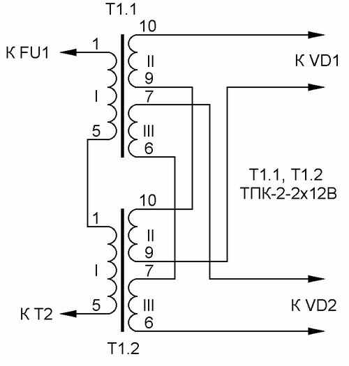
The transformer T1 is self-made, designed for the overall power of 3 W , which has a cross-sectional area of the magnetic circuit 1.87 cm2 . Its network winding I , designed for a maximum emergency voltage of 380 V , contains 8669 turns of PEV-2 wire with a diameter of 0.064 mm . Windings II and III contain 522 turns of PEV-2 wire with a diameter of 0.185 mm . At a nominal voltage of 220 V, the voltage of each output winding must be 12 V. Instead of the self-made transformer T1 , two TPK-2-2x12V transformers connected in series according to the method described in [2] can be used as shown in Fig .
The Pechat Stab-2.lay print file (the version with two TPK-2-2x12V transformers ) is made using the Sprint Loyout 4.0 program , which allows you to print the image in a mirror image and is very convenient for manufacturing printed circuit boards using a laser printer and iron . You can download it here .
Autotransformer T2 and self-made, wound on a toroidal magnetic circuit, which is used as a stator motor 10 kW in the manner described in [3] . Its winding contains 280 turns of PEV-2 wire with a diameter of 4.2 mm (cross section of 13.6 mm2 ). Such a cross section is necessary to ensure that the autotransformer is not heated during long-term operation. The bends are made from the 150, 163, 180, 195, 217 and 245th turns, counting from the bottom on the withdrawal scheme. The section of the winding to which the mains voltage is connected (branch line from the 180th turn) is rated at 380 V.
If the load power does not exceed 3 kW , the autotransformer T2 can be wound on a stator of an electric motor 4 kW with a PEV-2 wire 2.8 mm in diameter ( 6.1 mm2 cross-section). The number of turns of the winding should be increased proportionally by a factor of 1.2 . The operating current of the fuse switch QF1 must be reduced to 16 A. You can apply triac VS1-VS7 BTA140-800 , placed on the heat sink area of not less than 800 cm2 .
CONFIGURING THE STABILIZER
Installation is carried out with the help of LATR and two voltmeters. It is necessary to set the switching thresholds of the load and verify that the output voltage of the stabilizer is within the permissible limits for the equipment being fed. We denote U1, U2, U3, U4, U5, U6, U7 - voltage values on the engine of trimmer resistor R14 , corresponding to the mains voltage of 130, 150, 170, 190, 210, 230, 250, 270 V (switching thresholds and load cutoffs). Instead of trimmer resistors R15 and R23, permanent resistors with a resistance of 10 kΩ are temporarily mounted. Further, the stabilizer without an autotransformer T2 is connected to the network via the LATR . At the output of the LATR, the voltage is increased to 250 V , then the engine of the trimmer resistor R14 is set to the voltage U6 equal to 3.5 V , measuring it with a digital voltmeter. After that, lower the LATRA voltage to 130 V and measure the voltage U1 . Suppose, for example, that it is 1.6 V.
Calculate the voltage step :
ΔU = (U6 - U1) / 6 = (3.5-1.6) / 6 = 0.3166 V ,
Current flowing through the divider R15-R23
I = ΔU / R16 = 0.3166 / 2 = 0.1583 mA
The resistance of the resistors R15 and R23 is calculated :
R15 = U1 / I = 1.6 / 0.1833 = 10.107 kΩ ,
R23 = (Upit - U6 -ΔU) / I = (6-3,5-0,3166) / 0,1588 = 13,792 kOhm , where Upt is the stabilization voltage of the DA1 chip. The calculation is approximate, since it does not take into account the influence of resistors R32-R39 , but its accuracy is sufficient for the practical adjustment of the stabilizer.
Next, the device is disconnected from the network and using a digital voltmeter, the resistors R15 and R23 are set equal to the calculated values and mounted on the board instead of the permanent resistors mentioned above. The stabilizer is switched on again and the switching of the LEDs is tracked, gradually increasing the LATR voltage from minimum to maximum and back. Simultaneous illumination of two or more LEDs indicates a malfunction of one of the DA2, DA3, DD1-DD5 chips . A defective chip must be replaced, so it is more convenient to install on the board not the chips themselves, but panels for them.
Having convinced of the serviceability of the microcircuits, connect the autotransformer T2 and the load - an incandescent lamp with a power of 100 ... 200 W. The thresholds for switching and voltage U1-U7 are again measured. To check the correctness of calculations, changing the LATR input to T1, it is necessary to check the flashing of the HL1 LED at a voltage below 130 V , the successive activation of the LEDs HL2 through HL8 when crossing the switching thresholds indicated above, and flashing HL9 at a voltage above 270 V.
If the maximum voltage of the LATRA is less than 270 V , set at its output is 250 V , calculate the voltage U7 using the formula: U7 = U6 + ΔU = 3.82 V. Move the R14 engine up, check that the load is disconnected at U7 , and then return the R14 engine to the bottom, setting the previous value of U6 equal to 3.5 V.
Complete stabilization of the stabilizer is desirable by connecting it to 380 V for several hours.
During the operation of several copies of stabilizers of different capacities (approximately six months) there were no failures and failures in their operation. There was no malfunction of the equipment fed through them due to unstable mains voltage.
LITERATURE
1. Koryakov S. Stabilizer of network voltage with microcontroller control. - Radio, 2002, No. 8, p. 26-29.
2. Kopanev V. Protecting the transformer from overvoltage of the network. - Radio, 1997, №2 p.46.
3. Andreev V. Manufacture of transformers. - Radio, 2002, №7, p.58
print version
Author: Godin Aleksey Valerevich, Moscow
PS The material is protected.
Date of publication 26.01.2005гг
![]()

Comments
Commenting on, remember that the content and tone of your message can hurt the feelings of real people, show respect and tolerance to your interlocutors even if you do not share their opinion, your behavior in the conditions of freedom of expression and anonymity provided by the Internet, changes Not only virtual, but also the real world. All comments are hidden from the index, spam is controlled.