| Start of section
Production, amateur Radio amateurs Aircraft model, rocket-model Useful, entertaining |
Stealth Master
Electronics Physics Technologies Inventions |
Secrets of the cosmos
Secrets of the Earth Secrets of the Ocean Tricks Map of section |
  |
| Use of the site materials is allowed subject to the link (for websites - hyperlinks) | |||
Navigation: => |
Home / Inventions / Alternative energy / |
|
ETERNAL ELECTROHYDROUNDER TURBINE
FOR THE DEVELOPMENT OF CHEAP ENERGY FROM WATER IN THE CLOSED CIRCUIT
![]()
Leave a comment

ESSAY
A super economical power plant based on the original centrifugal water turbine and using the Yutkin electrohydraulic impact is proposed. It is designed to generate cheap mechanical and electrical energy separately or simultaneously by extracting and converting from the internal chemical energy of water or other liquid .
Its specific design may be different, but it must be carried out in a closed volume and must contain an electrohydrodynamic pressure supercharger in it by electric discharges in water that is tangentially tangential to the internal cavity of this turbine. This can be, for example, a conventional modernized centrifugal water pump supplemented with an electro-discharge chamber with tangential entry into the pump working cavity and a second muffled axial inlet. This simple, original, self-contained, reversible centrifugal pump containing a street stator, a rotor blade and a gong electric motor, supplemented with an electro-discharge chamber, makes it possible to directly convert the chemical energy of water and aqueous solutions to other types of useful energy and produce separately or simultaneously mechanical , electrical and thermal energy from water Through the effect of electrohydraulic shock in water, filled in the working chamber of the device.
This positive effect is achieved due to the introduction into the classical design of a centrifugal pump of an additional electro-discharge chamber connected hydraulically to one of its working holes, for example, with a tangential outlet in the spiral cochlear of the pump casing with a completely damped inlet axial hole of the pump casing, through an electro-discharge spark plug screwed into it Electric discharge -electrically when connected to an additional pulse frequency frequency converter, electrically connected to the battery and to the stator windings of the gon electric motor. Moreover, the gon electric motor, which is a part of the centrifugal pump, is transformed into a self- contained power generator in this autonomous power plant and generates electric power during spontaneous rotation of this electrohydraulic turbine.
Application for invention No. 2005117036/22 (018518)
Posol. FIPS Decision of 18.08.06
AUTONOMOUS ADVANCED CENTRIFUGAL PUMP
The utility model relates to machine building, engine building, electric power, heat power engineering, electrochemistry and can be used both fully and partially to produce certain types of useful energy ( mechanical, electrical and thermal ) from the chemical energy of water through centrifugal pumps and using electrohydraulic shock Effect of Yutkin .
Various methods and devices for converting water energy into other types of energy, for example, its kinetic energy into the mechanical energy of rotation of various hydro turbines, are known by using the energy of the water flow, for example, in hydroelectric power plants. However, these devices in the implementation are limited, because they require the presence of a flow of liquid, water and are very energy- and material-intensive in implementation.
There are known methods and devices for converting to thermal energy by chemical electrolysis of water with the production and subsequent combustion of H 2 and O 2 , simultaneously into thermal and electric energy by transferring it to a vapor state by means of heat supplied from the combustion of fuel and others. However, these well-known technical solutions of analogs do not allow the direct conversion of chemical energy of water into mechanical energy, are ineffective in terms of energy and cost, material intensity and payback periods.
The method and devices for direct conversion of the chemical energy of water into thermal energy by its forced rotation ( Ranke effect ) are known, however this method and devices are ineffective in output parameters and require an external supply of a considerable amount of electric power for the electric drive of the pump to create the effect of water rotation.
A method of direct conversion of the chemical energy of water into mechanical energy of the translational motion of a body is known (patent SU792003 ). The chemical energy of water is released in the known invention from water by an electric discharge in it and the formation of an electrohydraulic shock and the resulting pressure wave of fluid. This wave of water pressure and moves the piston of a well-known water motor. However, this invention, in spite of all its advantages, does not allow the direct transformation of the liquid pressure wave into rotation of the turbine.
Therefore, it does not allow direct conversion of the chemical energy of water in the closed and constant volume of the working chamber, in the kinetic energy of rotation of the mechanical working organ - the rotor of the turbine, which reduces its efficiency and significantly narrows its scope.
The purpose of the invention is to develop a useful model of the device, an electrohydraulic hydraulic turbine, for the direct conversion of the chemical energy of water into the kinetic energy of the rotation of a hydroturbine, for example a rotor blade of a modernized centrifugal pump, to generate kinetic , electric, and thermal energy from internal energy of water .
The closest device for the design and the same purpose to the claimed utility model for a set of characteristics is a typical hydraulic turbine, for example, made in the form of a standard centrifugal hydraulic pump. A standard centrifugal pump (prototype) comprising a hollow body with two working openings, one of which is a tangential outlet in the form of a spiral cochlea, and an inlet axial opening in the suction hub of the housing cover hydraulically coupled along the rotation axis to the cavity in the rotor for passage through To the rotor blades of the pumped liquid to the rotor blades, made in the form of a blade impeller fixed on a common shaft with a gon electric motor ( TSB, vol.2, p.616 , M., 1991 )
The essence of the prototype of a known centrifugal pump is that when the rotor is forced to rotate by a gon electric motor, the pump rotor blades pump the liquid through it. Which moves with acceleration from the inlet axial hole by the rotor blades to the tangential outlet of the pump. The kinetic energy from the impeller to the liquid is transferred through the dynamic interaction of the wheel blades with the fluid around them, which is captured by the rotor blades and thrown by the centrifugal forces to the periphery of the pump casing and then enters the cochlear of the pump casing and is discharged tangentially outward to form a passing fluid flow through this pump. The productivity of a centrifugal pump is regulated by changing the speed of rotation of the rotor. Moreover, to reduce leaks and increase the strength of the blade from the sides are closed discs of the pump casing.
With all the advantages of the prototype (simplicity and efficiency of operation), the scope of its application is rather narrow and it is intended only for pumping liquids, and for its operation a gong electric motor necessary for forced rotation of the blade rotor is required. Therefore, without the use of an energy-consuming gon electric motor, a known centrifugal pump can not operate in the reversible mode of a turbohydroelectric generator and can not produce mechanical electrical and thermal energy without external power supply from outside.
The object of the invention is to modernize a known device of a centrifugal pump, to produce mechanical, thermal and electric energy from water.
The technical result of this useful model consists in the technical improvement of the known device necessary to achieve the stated goal.
Said technical result is achieved by the fact that a known device of a centrifugal pump for pumping liquids comprising a stator and a rotor rotor disposed on a common shaft with a gong electric motor, and a coaxial inlet in the body and a rotor for introducing liquid into the pump and an outlet tangential opening in the stator, Is additionally provided with an electric discharge chamber, is damped from the outside, and on the other hand it is hydraulically connected to one of the working ports of the pump, the second working opening of the pump is sealed securely, and the entire working cavity of the stator and the discharge chamber is filled with a liquid, for example water, Is equipped with an electric spark plug screwed on its muffled end surface, and the central electrode of the spark plug is electrically connected through a boost pulse-frequency voltage converter to the battery and through the relay to the output of the windings of the stator of the engine.
The essence of the device
The proposed device based on a standard but improved centrifugal pump makes it possible to extract and use chemical energy from water by means of electric discharges in water with the subsequent formation of an electric shock effect in it ( the Yutkin effect ).
The device implementing this method, a reversible electrohydraulic turbine ( EGT ), consists essentially of three units:
- A standard hydraulic turbine, for example, a centrifugal pump with a tangential branch pipe of its body, embedded in the working cavity of the turbine.
- The floor of the electro-electric discharge chamber moved out of the water turbine (centrifugal pump casing), which has been muffled from the outside and connected hydraulically to it from the second working side through this tangential hollow tube in the pump casing, with the internal cavity of the pump casing, the entire working chamber containing two Of said element is filled with water or an aqueous solution.
- An electrical part containing a battery pack, a gong electric motor used in a reversible mode as an electric generator and a high voltage pulse voltage frequency converter connected to an output to the central electrode of an electric spark plug screwed into this electric discharge chamber, and electrically connected to the battery by an input And the stator windings of the above-mentioned electric motor.
The essence of the device
Rotation of the rotor and, together with it, of a rotary engine in the reversible mode of operation of this centrifugal pump is achieved by transferring a water pressure wave from an electrohydraulic impact from a separate electric discharge chamber ( ERC ) directly to the turbine rotor blades, for example, by transferring this pressure wave through the tangential input in the overhead The centrifugal pump casing, with the axial bore in the pump housing, or through the central axial inlet of the centrifugal retrofitted pump, with its second hole in the tangential branch pipe of the housing plugged.
The isolation and useful use of the internal chemical energy of water in the form of the energy of pressure in water and heat in it when the Yutkin effect is realized in it is carried out in a closed electrochemical cycle according to the formula 2H 2 O + electric discharge- = 2H 2 + O 2 -electric shock = 2H 2 O + 484KJ . In the completely closed volume of the water of the working chamber, which is converted directly into the kinetic energy of rotation of the rotor of the centrifugal pump, and, further, by electromechanical energy conversion from the common motor shaft operating in the electric generator mode to electricity, part of which is returned to the creation of electrical discharges In water, and other part of the generated electricity is useful for use in other electrical consumers. Moreover, water in such a device is a source of mechanical energy and, at the same time, a working body that ensures rotation of the rotor of a centrifugal pump in a closed volume of water, and at the same time a source of thermal energy , as it heats during cavitation and reduction processes in it during cyclic electrohydraulic attacks.
In Fig. 1, and 2 simplifies the proposed device, made constructively in the form of an upgraded centrifugal pump.
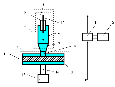
1 General block diagram of the device
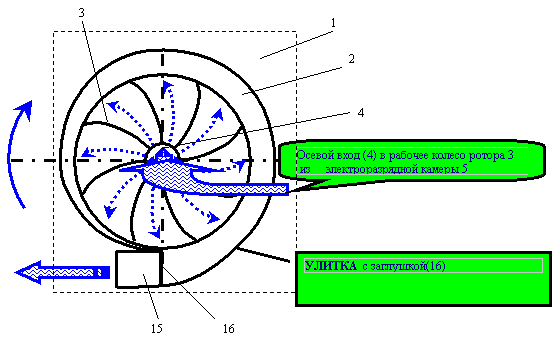
FIG. 2
FIG. 2 shows in more detail the stator and rotor structure of a modernized centrifugal pump (position numbering through in FIG . 1.2 ).
Description of construction
A standard centrifugal pump 1 consisting of a spiral-shaped, hollow shell (stator) 2 inserted into its blade rotor 3 with axial supply of liquid into it through an axial inlet 4 , supplemented by an electric discharge hollow chamber 5 with a working cylinder 6 , muffled from the outside, and An outlet nozzle 7 hydraulically tightly connected to the inlet pipe 4 of the pump 1 , and an electric spark plug 8 containing an electrical insulator 9 and high-voltage electrodes 10 (for simplicity, only one electrode is shown) is electrically connected through an end face of the cylinder 6 of the discharge chamber 5 (screwed) A controllable boost pulse-frequency voltage converter 11 to the battery 12 and via a relay (not shown) to the windings of the motor 13 located on the common shaft 14 with the rotor 3 of the pump 1 , the tangential terminal 15 of the housing 2 of the pump 1 sealed and firmly closed And the entire working space of the hollow closed chamber, including the hollow body 2 , the rotor 3 and the hollow discharge chamber 5 , is filled with a liquid, for example water.
In another embodiment of the device based on the modernized centrifugal pump 1, the discharge chamber 5 can be hydraulically connected to the tangential branch pipe 15 , and the plug 16 , in this embodiment of the device, is placed on the inlet 4 to form a completely closed working chamber with water.
In a particular case of a different embodiment of the device for intensifying heat generation in water during electrohydraulic attacks and the use of the thermal energy of the liquid, the device is provided with an open tangential outlet 15 of the housing 2 connected by a closed loop of the pipeline containing heat radiators from the tangential outlet 14 to additional tangential entry into the working cavity The stator housing 2 of the pump 1 (not shown) or to the discharge chamber 5 through an additional tangential entry into the working cylinder 6 (not shown in Figures 1, 2 ), the nozzle 7 being designed as a Laval cavitation nozzle for intensifying heat generation in Water from intensive cavitation at cyclic pressure waves.
The device works as follows
First, a battery 12 is connected to the pulse frequency frequency converter 11 by applying high voltage pulses to its high voltage output, through an electric spark plug 8 with an electrode 10 immersed in water, an electric discharge chamber 5 filled with water. As a result, with electric discharges in the water, a sufficient amount of electric current and spark power in the chamber 6 , an electrohydraulic impact of the liquid (water occurs, and the powerful water pressure wave generated from it is transmitted through the focusing nozzle 7 and the inlet 4 to the rotor blades 3 in the cavity of the pump 1 By adjusting the electric discharge current, the frequency and the duration of the electrical discharges in the chamber 6 from the voltage converter unit 11, and the power and the possibility of electrohydraulic attacks in the water, and as a consequence - regulate the power, the rotational torque of the rotor on the shaft 14 and the speed of rotation of the rotor 3 . In this case, the electric machine 13 , rotating together with the rotor 3 and from the rotor energy, starts to operate in a reversible generator mode (the self-excitation and parameter adjustment unit of the generator is not shown) and begins to generate electricity, converting part of the kinetic energy of rotation of the rotor 3 into electrical energy by an electric generator. The winding of the electric generator 13 is electrically connected via a relay (not shown) to the voltage converter 11 and to the autonomous source 12 (not shown for recharging this battery. Since water during this process of electrical discharges and electrohydraulic attacks intensively heats up in a closed working cavity, its heat can be useful to use by removing it through additional external heat exchangers (not shown) from the surface of the pump bodies 2 and the electric discharge chamber 5 .
Thus, the proposed autonomous reversible centrifugal pump makes it possible to provide an efficient direct conversion of the chemical energy of water through the electrohydraulic effect of electrical discharges in water to other types of useful energy.
The proposed useful model has already been partially tested in laboratory experiments.
CLAIM
An autonomous, reversible centrifugal pump comprising a hollow shell in the form of a cochlea with two working holes therein, one of which is an output tangential opening and the second an inlet axial hole hydraulically connected to the rotor blade and a rotor motor on the rotor shaft, characterized in that The pump is further provided with a hollow cylindrical electrohydrodischarge chamber plugged from the outer end and hydraulically connected to one of the aforementioned holes of the centrifugal pump, the second working opening being securely and firmly sealed, and the entire working cavity of the pump casing and the discharge chamber filled with liquid, for example water, And an electric spark plug is screwed into the body of the electric discharge chamber, electrically connected via an adjustable pulse-frequency voltage converter to the battery and to the stator windings of the gonor electric motor.
print version
Author: VD Dudyshev, Academician of REA
Date of publication 01.10.2006гг
![]()

Comments
Commenting on, remember that the content and tone of your message can hurt the feelings of real people, show respect and tolerance to your interlocutors even if you do not share their opinion, your behavior in the conditions of freedom of expression and anonymity provided by the Internet, changes Not only virtual, but also the real world. All comments are hidden from the index, spam is controlled.