
| Start of section
Production, amateur Radio amateurs Aircraft model, rocket-model Useful, entertaining |
Stealth Master
Electronics Physics Technologies Inventions |
Secrets of the cosmos
Secrets of the Earth Secrets of the Ocean Tricks Map of section |
  |
| Use of the site materials is allowed subject to the link (for websites - hyperlinks) | |||
Navigation: => |
Home / Patent catalog / Catalog section / Back / |
|
INVENTION
Patent of the Russian Federation RU2246634
![]()
WIND ROTOR
The name of the inventor: Popov Maxim Alexandrovich (RU); Popov Denis Alexandrovich (RU); Popov Alexander Ilyich
The name of the patent holder: Popov Maxim Aleksandrovich (RU); Popov Denis Alexandrovich (RU); Popov Alexander Ilyich
Address for correspondence: 620049, Ekaterinburg, per. Avtomatiki, 2, JSC "Plant Promavtomatika", for A.I. Popova
The effective date of the patent: 2003.03.17
The invention relates to the field of wind energy and can be used to obtain mechanical or electrical energy. The technical result consists in increasing the coefficient of energy consumption of the flow and simplifying the scheme for regulating the rotor speed. In a rotor of the Ugrinsky rotor type comprising a pair of blades disposed symmetrically on the disk relative to its axis of rotation, according to the invention, a second pair of blades is further introduced and the working surfaces of the segments are formed for the gas or liquid flow from the points of intersection of both pairs of blades to their end at the periphery of the disk, And for the flow of the flow, through channels are formed by removing portions of the blades between the points of their intersection near the center of rotation.
DESCRIPTION OF THE INVENTION
The present invention relates to wind turbines and can be used to generate mechanical or electrical energy.
Known structures of a similar purpose, converting the energy of the air or water flow into rotary motion [1, 2, 3, 4].
Such rotary and rotary engines with a vertical axis of rotation have a low energy utilization factor of the gas or liquid flow, since they are driven into rotation only by a part of the flow moving in passing, for example, the windward blades.
Also known are rotors of the Savonius and Kazhinsky type, in which the energy of the part of the stream already used at the pressure on the blade reflects from it and represses the other blade, which increases the wind turbidity consumption coefficient [5, 6, 7, 8].
However, this kind of device does not evenly perceive the pressure of the flow from different directions, i.e. Have non-working ("dead") zones, so to ensure the uniformity of their rotation, use two or more similar rotors located on a common axis, but their blades are shifted by a certain angle.
The closest in terms of technical nature to the claimed device is the rotary turbine of the Ugrynsky system [9] chosen as a prototype, containing a pair of blades located on the disk symmetrically with respect to the rotation axis of the rotor. In this rotor, as well as in the Savonius rotor, the secondary reflected flow is partly used, and due to the specific configuration of the blades the non-working zone is reduced [9, pp. 30, 31, 32].
However, the prototype has the same drawback: a low coefficient of energy flow because of its uneven movement through the rotor and the unequal reaction of different parts of the blade to the flow, which increases its turbulence, which ultimately reduces the torque. In addition, the prototype does not regulate the speed depending on the speed of the wind.
The technical advantages of the claimed object in comparison with the known devices are as follows:
- In addition, a second pair of blades is introduced, and the working surfaces of the segments are formed for the flow of liquid or gas from the points of intersection of both pairs of blades to their end at the periphery of the disk, four flow paths (instead of one in the prototype) formed by the removal of the blade sections between the points Their intersection near the center of rotation. This increased the volume of use of the secondary reflected stream.
- On the working surface of the segments formed due to the intersection of two pairs of blades, normally closed valves are executed in the direction to the center of its rotation, and a part of the energy of the flow passes through the second one.
- The segments are located on additional bases having a rotational axis with a pinion, the gears being connected by means of a mechanical transmission with a speed controller, which makes it possible to select the optimum rotor operation mode with the available wind speed.
This makes it possible to extend the used range of wind or water flow rates at which the rotor is operative, improve the uniformity of its rotation, and optimally use the energy of the flow by regulating the revolutions in the automatic mode.
The combination of these technical advantages of the claimed object will provide a positive effect, which consists in increasing the coefficient of energy consumption of the flow and simplifying the regulating the speed of the rotor.
 |
 |
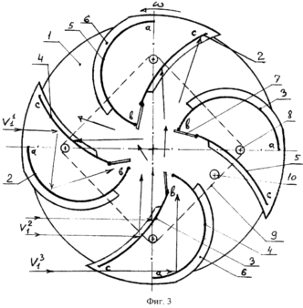 |
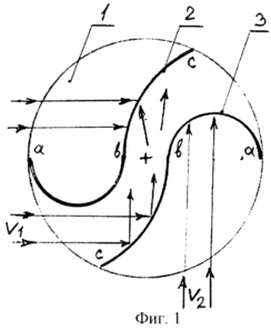
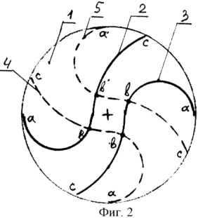
1 shows the distribution of a gas or liquid flow in a Ugrinsky rotor turbine. FIG. 2 is a schematic diagram of the formation of a rotor proposed by the inventor; FIG. 3 shows a rotor (general view). FIG. The rotor has a disk 1, on which the blades 2, 3, 4, 5 are mounted, located on the disk symmetrically relative to its axis of rotation (the upper disk may be absent). Parts of the intersecting blades 2, 3, 4, 5 form segments that can be placed on their bases 6. Normally closed, spring-loaded valves 7 are provided on the working surface of the blades 2, 3, 4, 5 segments towards the center of the rotor. Segments together with the bases have The possibility to rotate on their axes by means of gears 8 connected by a common mechanical transmission 9 to a gear 10 of a standard centrifugal speed controller (not shown). The rotor works as follows. 1 shows the possible distribution in the prototype of the flows V 1 and V 2 from different directions of the rotor. The tests of the layouts according to Ugrynsky's schemes establish that the direction of V 1 is more preferable than V 2 , since the flux is reflected twice, creating a greater torque, first from the arc "cb" of the blade 3, and then, after the center of rotation, from the arc "bc" of the blade 2. In addition, the flow that passes through the through channel through the center of rotation has a higher speed than the flow inhibited by the semi-cylinders "b" of the blades, which creates vortices that prevent laminar flow, which as a result reduces the efficiency of the device. |
The pairs of blades 4, 5, when intersected with the blades 2,3 of the Ugrynsky system, form four curvilinear segments "abc", with four sections of blades "bb" between the points of their intersection being removed. As a result, four curvilinear "abbc" channels are formed to move the flow of liquid or gas.
From the "V" direction (FIG. 3), the maximum of the flow energy is used: part of the flow "V 11 " passes through the segment formed by the lengths of the blades 2, 4 and through its opened valve 7, the other main part of the flow V 21 passes through the channel Between the blades 2, 3 and an insignificant part of this flow "V 31 " comes to the center of the rotor through a segment formed by a part of the blades 3, 4 and its valve 7. A part of the flow "V 21 " is reflected from the arc "CB" of the blade 3 , And the total flow "V1", i.e. (V 11 + V 21 + V 31 ), after passing the center of rotation of the rotor, is reflected both from the arc "c" of the blade 4 and from the arc "cv" of the blade 2, creating in both cases a torque of one direction " ![]() ". In the indicated position of the rotor, the spring-loaded valves 7 of the other two segments are closed.
". In the indicated position of the rotor, the spring-loaded valves 7 of the other two segments are closed.
In order to regulate the speed, the segments are placed on separate movable bases 6 mounted on the axis with the gears 8. When the specified rotor speed from the centrifugal regulator (not shown) is exceeded, torque is transferred to the gear of the common drive of the mechanical transmission (chain) 9, Simultaneous action on the gears 8 of all four segments turns them one way up to the closing (touch) of the segments. The extreme position "Clamping of rotors" is also used when they are stopped for repair or maintenance.
For comparative tests, three layouts of the same dimensions were made: the Savonius rotor, the Ugrinsky rotor and the rotor according to the present application. Measurements of wind speed were made by an anemometer AP 1M, measurements of the number of revolutions per minute by an ATT6000 phototaximeter.
As a result of laboratory tests it was found out that the typical Savonius rotor had a starting wind speed of 3,0 ... 3,2 m / s, the Ugrinsky rotor - 2,3 ... 2,8 m / s, and the proposed rotor - 1,4 ... 1.8 m / s.
At the maximum wind speed of about 15 m / s obtained in laboratory conditions, the rotor developed 590 rpm. Manual repositioning of the segments allowed to obtain a given number of revolutions at different wind speeds, which confirms the possibility of automatic regulation.
Industrial development of such engines significantly expands the field of their application for wind power, for the creation of mini hydropower plants, and others.
INFORMATION SOURCES
1. Description of the invention to the author's certificate of the USSR № 992800, cl. F 03 D 3/00 (analog).
2. Description of the invention to European Patent WO 95/08062, Form B (analog).
3. Description of the invention to the USSR copyright certificate №1663226, cl. F 02 D 3/06 (analogue).
4. Description of the invention to the author's certificate of the USSR № 1017814, cl. F 03 D 3/00 (analog).
5. Description of the invention to the author's certificate of the USSR №1553758, cl. F 03 D 7/06, Wind turbine (analog).
6. Description of the invention to the author's certificate of the USSR № 1612109, cl. F 03 D 7/06. Windmill rotor (analog).
7. Description of the invention to the RF patent No. 218703, cl. F 03 D 3/00. Rotary wind turbine (analog).
8. B.V. Kazhinsky. Free-flow hydroelectric power plants of low power. Under. Ed. Berg, vol. 57, M., 1950, p.31, FIG. 10 (analog).
9. B.V. Kazhinsky. Free-flow hydroelectric power plants of low power. Ed. Berg, vol. 57, M., 1950, p. 32, 33, Figures 11 and 12 (prototype).
CLAIM
A rotor of the Ugrinsky rotor type comprising a pair of blades disposed symmetrically on the disk relative to its axis of rotation, characterized in that the second pair of blades is further introduced and the working surfaces of the segments are formed for the gas or liquid flow from the points of intersection of both pairs of blades prior to their termination at the periphery Disk, and for the flow of the flow through channels are formed due to the removal of sections of the blades between the points of their intersection near the center of rotation.
2. A rotor according to claim 1, characterized in that normally closed valves are formed on the working surface of the segments formed from the intersection of the blades of the segments in the direction to the center of its rotation.
3. A rotor according to claim 1, characterized in that the segments are located on additional bases having an axis of rotation with a pinion, all gears being connected by means of a mechanical transmission with a speed controller.
print version
Date of publication 02.02.2007gg
![]()

Comments
When commenting on, remember that the content and tone of your message can hurt the feelings of real people, show respect and tolerance to your interlocutors even if you do not share their opinion, your behavior in the conditions of freedom of expression and anonymity provided by the Internet, changes Not only virtual, but also the real world. All comments are hidden from the index, spam is controlled.