
| Start of section
Production, amateur Radio amateurs Aircraft model, rocket-model Useful, entertaining |
Stealth Master
Electronics Physics Technologies Inventions |
Secrets of the cosmos
Secrets of the Earth Secrets of the Ocean Tricks Map of section |
  |
| Use of the site materials is allowed subject to the link (for websites - hyperlinks) | |||
Navigation: => |
Home / Patent catalog / Catalog section / Back / |
|
INVENTION
Patent of the Russian Federation RU2162532
![]()
AUTONOMOUS STIRLING-INSTALLATION FOR SIMULTANEOUS
PRODUCTION OF ELECTRICITY AND HEAT
The name of the inventor: Kirillov N.G.
The name of the patent holder: Military Space Engineering University. A.F. Mozhaisky
Address for correspondence: 197082, St. Petersburg, P-82, ul. Red Kursanta, 16, Military Space Engineering University. A.F. Mozhayskogo, NIO, NIL-6, Kirillov N.G.
Date of commencement of the patent: 1999.09.30
The invention relates to the field of heat power engineering and Stirling engines, is intended as autonomous power plants for stationary and mobile objects with simultaneous production of electricity and heat.
The technical result achieved is an increase in efficiency and a reduction in the mass-dimension characteristics of an autonomous installation as a whole. In operation, the engine 1 produces useful energy converted into electrical energy by means of an electric generator 5 located on the same shaft as the engine 1. To cool the engine 1, the cooler 9 is supplied with water from the cooling system 9 connected to the external heat supply system 10 through the heat exchanger 9 and the line Of the tap water 14 through the heat exchanger 16. The water from the water main 12 is partially supplied to the steam generator 6 through the heat exchanger 16, partly to the steam-water pump-heater 7 through the heat exchanger 8. High-pressure steam from the steam generator 6 via the line 19 enters the steam-water pump-heater 6, With water coming from line 17, forming water with high temperature and pressure. Due to this pressure, hot water is supplied through mains 20 of the hot water supply system. The exhaust gas duct 4 from the combustion chamber 2 passes through the steam generator 6 and the heat exchanger-heat exchanger 8.
DESCRIPTION OF THE INVENTION
The invention relates to the field of heat power engineering and Stirling engines, is intended as autonomous power plants for stationary and mobile objects with simultaneous production of electricity and heat.
It is known to provide a power plant comprising an internal combustion engine (ICE) with a power consumer shaft through a coupling and a recycling steam turbine plant with a working fluid circulation circuit including a steam turbine, a condenser, a feed pump, a steam generator located in the high-temperature exhaust gas engine No. 1677360. The Bulletin of Inventions No. 34 of 15.4.91, pp. 141-142). However, this device is not designed to generate heat for heat supply to external consumers and uses a low-efficiency direct-cycle converter - ICE.
It is known to use a steam-water pump-heater (PNP) designed for use in various industrial technologies using steam, which combines the functions of the heater and the pump simultaneously. The application of PNP allows to significantly reduce the energy consumption for own needs and reduce the mass-dimensional characteristics of heat exchangers (Energy Petersburg / newspaper /, No. 5 (11), dated May 25, 1999). However, previously steam-water pump-heater in cogeneration plants was not used.
It is known that autonomous energy sources based on Stirling engines ensure high efficiency and reduce the concentration of harmful emissions in exhaust gases (Kirillov NG Application of highly efficient and environmentally friendly Stirling machines in ship power engineering.) Proceedings of the 2nd International Conference on Marine Intellectual Technologies "Morintech-97" /, Volume N 5, St. Petersburg 1997, p. 140) . However, to increase the efficiency of the Stirling engine, it is necessary to use a coolant with a minimum temperature.
The Stirling engine device is known, which includes a combustion chamber, a heater, a regenerator, a refrigerator, a piston group and a drive (G. Reader, C. Hooper, Stirling engines, M., Mir, 1986, p. 55) .
There is a combined installation based on the Stirling engine with an electric generator on one shaft , fuel supply lines and a heat exchanger for heating the liquid through which the exhaust gases of the Stirling engine pass , while the heated liquid is transferred to external lines (EPO application No. 0457399. Abstract journal "The invention of the countries of the world" ", Issue B-65, No. 5, 1993, p. 13). However, this unit has a complex system for co-cooling the engine and generator, and, and it is not designed to generate steam for use in external heat supply systems.
It is known that a cogeneration unit is designed to simultaneously generate electricity and heat , including an internal combustion engine with an electric generator on one shaft, fuel supply lines, an engine cooling circuit, a heating circuit (heat supply system with heat consumers), a heat exchanger system providing heat transfer from the cooling Engine fluid and high-temperature exhaust gases into the heating circuit, and control panel ("Building Review" // Journal of Quality //, SPb., No. 5 (32), May-June 1999, p. 16-17). However, this device does not presuppose the production of steam and its use to reduce electricity consumption for own needs, and, as a direct-cycle converter, an internal combustion engine with low efficiency and a high concentration of harmful substances in the exhaust gases is used.
The technical result that can be obtained in the implementation of the invention is to increase the efficiency of the installation, by reducing the energy consumption for own needs and applying a more efficient thermodynamic cycle of the direct-cycle converter - the Stirling cycle, and reducing the mass-size characteristics of the stand-alone installation as a whole.
In order to achieve this technical result, an autonomous styrling installation for simultaneous production of electricity and heat , including a direct-cycle converter (motor) with an electric generator on one shaft, fuel supply lines, a heat exchanger-heat reclaim heat generator of high-temperature exhaust gases through which the exhaust gas line passes Engine, the engine cooling system connected through a heat exchanger with an external heat supply system is equipped, as a straight-line converter, with a Stirling engine , a heat exchanger-utilizer of high-temperature exhaust gases from the Stirling engine , in the form of a steam generator, a steam-water pump, a waste heat exchanger, low-temperature exhaust gas heat exchanger Stirling engine , a heat exchanger-cooler, and a water main with a regulating valve, divided into a line with a control valve, passing through the heat exchanger-cooler to the steam generator, and a line with a control valve passing through the heat exchanger of the low-temperature exhaust gases of the Stirling engine in the steam- A high-pressure steam line running from the steam generator to the steam-water pump-heater and the main of the hot water supply system running from the steam-water pump-heater, while the Stirling engine exhaust gas line passes first through the steam generator and then through the heat exchanger-utilizer of the low-temperature Of the exhaust gases.
Introduction to the Stirling engine as a stand-alone unit for the simultaneous production of electricity and heat, as a direct-cycle converter, heat exchanger for high-temperature exhaust gases from the Stirling engine made as a steam generator, steam-water pump-heater, heat exchanger for low-temperature waste gases from the Stirling engine , Heat exchanger-cooler, and, the lines of the water pipe, passing respectively through the heat exchanger-cooler to the steam generator and through the heat exchanger-utilizer of low-temperature gases in the steam-water pump-heater, the high-pressure steam lines, the hot water supply lines, allows to obtain a new property consisting in The possibility of using the heat of the Stirling engine cooling system for heat supply to external heat consumers, and the residual heat of the exhaust gases of the Stirling engine for hot water supply, at the same time high-pressure steam is generated for its further use to replace network pumps and heat exchangers in the hot water supply system, and part of the water From the water main is used to reduce the temperature of the coolant to cool the Stirling engine .
The figure shows an autonomous styrling installation for simultaneous production of electricity and heat.
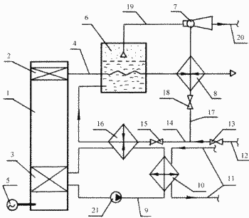 |
The self-contained washing unit includes a Stirling engine 1 with a combustion chamber 2 and a cooler 3, an exhaust gas line 4, an electric generator 5 located on the same shaft as the engine 1, a high-temperature exhaust gas heat exchanger, a steam generator 6, a steam-water pump A preheater 7, a low-temperature exhaust gas heat exchanger 8, a cooling system 9 of the engine 1 passing through the cooler 3 and connected via a heat exchanger 10 to an external heat supply system 11, a tap water line 12 with a control valve 13 divided into a line 14 with a control valve 15 And a heat exchanger-cooler 16 through which the cooling system 9 passes into the steam generator 6 and a line 17 with a control valve 18 passing through the waste heat exchanger-low-temperature exhaust gas 8 to the steam-water pump-heater 7, the high-pressure steam pipe 19 going From the steam generator 6 to the steam-water pump-preheater 7, and the main 20 of the hot water supply system. A pump 21 is provided for circulating the cooling liquid in the cooling system 9 of the engine 1. |
The stand-alone styrling installation for simultaneous production of electricity and heat works as follows.
In operation, the engine 1 produces useful energy converted into electrical energy by means of an electric generator 5 located on the same shaft as the engine 1. To cool the engine 1, the cooled water of the cooling system 9 is supplied to the cooler 3. The cooling system 9 is connected through the heat exchanger 10 to the external heat supply system 11 and through the heat exchanger 16 to the water supply line 14. Tap water, through the control valve 13, through the line 12 enters the lines 14 and 17. The water through The water line 14 passes through the heat exchanger-cooler 16 where it cools the cooling fluid of the cooling system 9 of the engine 1 to the minimum temperature while heating itself and entering the steam generator 6 where it is evaporated by heat exchange with the high-temperature exhaust gases from the combustion chamber 2 along the line 4. Water through line 17 passes through heat exchanger-utilizer of low-temperature exhaust gases 8, where it is heated by residual heat of low-temperature exhaust gases coming from steam generator 6, and enters steam-water pump-heater 7 into which steam generator 6, along highway 19, High pressure steam. In the steam-water pump-heater 7, due to the special design and effect of mixing two-phase vapor-liquid media, pressure increases, intensive mixing of steam and water, followed by the production of hot water with a high temperature (up to 100 degrees Celsius) and pressure. Due to this pressure, hot water is supplied through line 20 to the hot water supply system. Regulating valves 13, 15, 18 are provided for regulating the flow of water.
INFORMATION SOURCES
Author's svid. N 1677360. Bulletin of Inventions No. 34 of 15.4.91, pp. 141-142.
"Energy of Petersburg" // newspaper //, N 5 (11), from 25.05.99
Kirillov N.G. Application of highly efficient and environmentally friendly Stirling machines in ship power engineering. / Proceedings of the 2-nd Intl. Confer. On marine intellectual technologies "Morintech-97" /, Volume N 5, SPb., 1997, p. 140.
G. Reader., C. Hooper. Stirling engines . M., ed. "The World", 1986, p. 55.
EPO application No. 0457399. Abstract journal "The invention of the countries of the world", issue B-65, No. 5, 1993, p. 13.
"Building Review" // Journal of Quality //, SPb., No. 5 (32), May-June 1999, pp. 16-17 - prototype.
CLAIM
Stand-alone unit for simultaneous production of electricity and heat, which includes a direct-cycle converter (motor) with an electric generator on one shaft, fuel supply lines, heat exchanger-heat reclaimer of high-temperature exhaust gases of the engine through which the engine exhaust line passes, engine cooling system , Which is connected through a heat exchanger with an external heat supply system, characterized in that it is equipped with a Stirling engine as a direct-cycle converter, a Stirling engine heat exchanger for high temperature exhaust gases, a steam generator , a steam-water pump-heater, a heat exchanger for low-temperature exhaust gases from the Stirling engine , Heat exchanger-cooler, and a water main with a control valve, divided into a line with a regulating valve, passing through a heat exchanger-cooler into the steam generator, and a line with a control valve passing through the heat exchanger of the low-temperature exhaust gases of the Stirling engine in the steam-water pump-heater, A high-pressure steam from the steam generator to the steam-water heating pump and the hot water main running from the steam-water heater pump, the Stirling engine exhaust gas line passing first through the steam generator and then through the heat exchanger of the low-temperature exhaust gas.
print version
Date of publication 05.11.2006гг
![]()

Comments
When commenting on, remember that the content and tone of your message can hurt the feelings of real people, show respect and tolerance to your interlocutors even if you do not share their opinion, your behavior in the conditions of freedom of expression and anonymity provided by the Internet, changes Not only virtual, but also the real world. All comments are hidden from the index, spam is controlled.