

| Start of section
Production, amateur Radio amateurs Aircraft model, rocket-model Useful, entertaining |
Stealth Master
Electronics Physics Technologies Inventions |
Secrets of the cosmos
Secrets of the Earth Secrets of the Ocean Tricks Map of section |
  |
| Use of the site materials is allowed subject to the link (for websites - hyperlinks) | |||
Navigation: => |
Home / Patent catalog / Catalog section / Back / |
|

INVENTION
Patent of the Russian Federation RU2074475

CAPACITOR-KINETIC ENERGY STORAGE EQUIPMENT
The name of the inventor: Polyashov, L.I. Ivanov AM; Gerasimov A.F.
The name of the patent holder: Limited Liability Partnership MNPO "Ekond"
Address for correspondence:
Date of commencement of the patent: 1994.08.01
Use: in electrical engineering, in systems of accumulation of the electric power, containing mechanical and electric energy stores. SUMMARY OF THE INVENTION: A capacitor bank assembled from series-parallel switched ultra-high energy capacitor capacitors is structurally fixed to the flywheel on its periphery, the battery terminals of the corresponding polarity are connected to the contact rings mounted on the flywheel shaft and equipped with a brush-contact apparatus for insertion into the electric power circuit cars.
DESCRIPTION OF THE INVENTION
The invention relates to electrical engineering, and more particularly to power storage systems comprising mechanical and electrical energy storage devices.
Widely known means for short-term energy storage : the flywheel (kinetic energy storage), capacity (the accumulation of energy in the electrostatic field) and inductance (the accumulation of energy in the electromagnetic field).
The degree of efficiency of the flywheel as an energy storage device depends on its size and mass , and on the frequency of its rotation and the range of its changes, due to which the accumulation and release of kinetic energy occurs. But in comparison with the inductance and capacity, the flywheels have a stored energy density tens of times to hundreds of times and are used in electric drives with impact load (rolling mills, stamps, etc.) and vehicles.
On the other hand, the use of a flywheel in an electromechanical system is possible only if there is an energy converter on its shaft, which makes this method of storage suitable for relatively low power ( see, for example, "Rayway Gazette", September, 1976 ). Therefore, for small amounts of accumulated energy, inductance and capacity as a storage device become more economical than a flywheel. They are included in the power circuit of the electrical machine.
For the long-term accumulation and consumption of electricity, the most suitable means are known to be chemical sources of current of one type or another, including accumulators.
There are also known technical solutions for electric vehicles with a hybrid drive , which include kinetic (flywheel) and capacitive power storage equipment in the equipment to increase the amount of stored energy during braking and improve the dynamic qualities of an electric vehicle when using a chemical source of current as the primary source of electricity ( see, for example, Automotive Industry of the USA, 1993, N 3, p. 3 ).
The use of capacitive storage is becoming effective due to the development in Russia and abroad of capacitors with a double electric layer, which have been called in Russia impulse capacitors of ultrahigh energy capacity ( IKE ). They most meet the requirements for energy and power densities imposed on power storage devices for vehicles.
The object of the invention is to provide a capacitive-kinetic storage with a high energy density that constructively combines a capacitor bank and a flywheel and combines their advantages.
This object is achieved by the fact that in a capacitive-kinetic energy storage device comprising a capacitor bank included in the power circuit of an electric DC machine and a flywheel whose shaft is coupled to its shaft via a clutch and mechanical transmission, according to the invention, the capacitor bank is assembled from a series- Parallel connected pulse capacitors of ultrahigh energy capacity and is structurally integrated with the flywheel by fixing it on its peripheral surface, and the battery terminals of the corresponding polarity are connected to the contact rings, each of which is mounted on the flywheel shaft and equipped with a brush-contact device for inclusion in the power circuit of the electric machine.
Distinctive features of the proposed capacitive-kinetic storage in comparison with the known storage devices are :
- The capacitor bank is assembled from series-parallel-connected ITSs ;
- The IKE is fixed on the peripheral surface of the flywheel;
- The terminals of the corresponding polarity of the capacitor bank are connected to the contact rings;
- Each contact ring is mounted on the flywheel shaft and is provided with a brush-contact device for connection to the electric machine chain.
At the same time, the density of accumulated electric energy ( kJ / kg ) is increased due to an increase in the energy storage of the accumulator, since the amount of energy of the flywheel and the capacitor bank is summed and their total mass is reduced, since the IES with an energy reserve of 40-60 kJ or more is, as a rule, A tangible share in the mass of vehicle equipment, are combined with the flywheel and participate in the accumulation of kinetic energy by the flywheel. The connection of the terminals of the capacitor bank of the corresponding polarity to the contact rings mounted on the flywheel shaft and equipped with a brush-contact device allows the capacitor bank to be inserted into the capacitor-kinetic storage circuit with the least losses.
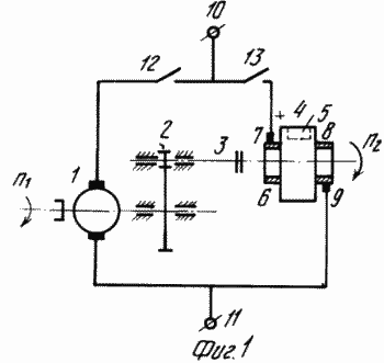 FIG. 1 shows a basic electrical and structural diagram of a capacitive-kinetic storage device according to the invention |
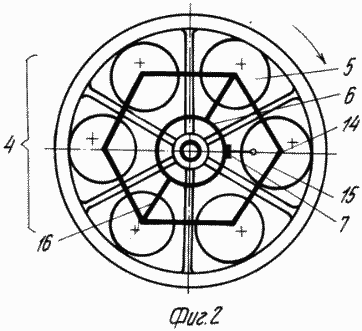 FIG. 2 is a variant of a structural combination of a flywheel with a capacitor bank according to the invention. FIG. |
The storage device comprises a DC electric motor of independent excitation or with a permanent magnet 1 rotating at a speed n 1 , a mechanical transmission 2, a clutch 3, a flywheel 4, on the peripheral surface of which capacitors 50 are assembled into a capacitor bank With a battery of 6 capacitors). On the shaft of the flywheel 4 rotating at a frequency of n 1 , a positive-polarity contact ring 6 with a brush-and-pinion device is installed. 9. The accumulator terminals 10 and 11 serve to connect it to an electromechanical system where the accumulation of electrical and kinetic energy is required. To extend the functionality, the electrical circuit of the drive includes switches 12 and 13. The terminals of the capacitors 5 of the same polarity 14 are connected by the bus bars 15 to the battery, each terminal 16 of which is connected to a corresponding contact ring 6 and 8.
CAPACITOR-KINETIC DRIVER WORKS AS FOLLOWS:
When the terminals 10 and 11 are connected to the electromechanical system and the switches 12 and 13 are closed, the electric machine 1 operates in the engine mode and, with the machine shafts 1 and the flywheel 4 interlocked by the mechanical transmission 2 and the coupling 3, untwists it to the rotational speed n 2 , charging it with a kinetic Energy. At the same time, with the switch 13 closed, the capacitor battery charges from the power source of the electromechanical system through the electric circuit through the brush-and-pinion device.
When the operating mode of the electromechanical system changes, when the electric machine 1 switches to the generator mode, the energy of the capacitor bank is discharged along the same electrical circuit as the machine 1 and the electromechanical system. Simultaneously, the accumulated kinetic energy of the flywheel is converted by means of machine 1 to electric and is returned to the electromechanical system.
The capacitance-kinetic storage has a wider functionality compared to the individual flywheel and capacitor bank. So when the key 12 or 3 is open, the flywheel is stationary and only the capacitor bank is functioning as a storage device. On the other hand, when the key 13 is open, the capacitor bank does not function as a storage device. Thus, depending on the algorithm of operation of the electromechanical system, it is possible to use the accumulated energy optimally (including batch).
The proposed invention can be effectively used in vehicles with electromechanical transmission (electric vehicles, "zhirobuses", urban transport, electric locomotives for pumping coal, shunting ships in harbors, etc.).
CLAIM
A capacitive-kinetic energy storage device comprising a capacitor bank included in the power circuit of an electric DC machine and a flywheel whose shaft is coupled to its shaft through a mechanical transmission and a clutch, characterized in that the capacitor bank is assembled from series-parallel-coupled pulse capacitors of ultra high Energy intensity and is structurally integrated with the flywheel by fixing it on its peripheral surface, and the battery terminals of the corresponding polarity are connected to the contact rings, each of which is mounted on the flywheel shaft and equipped with a brush-contact device for inclusion in the power circuit of the electric machine.
print version
Date of publication 19.11.2006гг


Comments
When commenting on, remember that the content and tone of your message can hurt the feelings of real people, show respect and tolerance to your interlocutors even if you do not share their opinion, your behavior in the conditions of freedom of expression and anonymity provided by the Internet, changes Not only virtual, but also the real world. All comments are hidden from the index, spam is controlled.