

| section Home
Production, Amateur Radio amateur Model aircraft, rocket- Useful, entertaining |
Stealth master
Electronics Physics Technologies invention |
space Mystery
Earth Mysteries Secrets of the Ocean Stealth section Map |
  |
| Use of material is permitted for reference (for websites - hyperlinks) | |||
Navigation: => |
Home / Products Patents / In the section of the catalog / back / |
|

INVENTION
Russian Federation Patent RU2272965

Autonomous heating
Name of the inventor: Valery Serov (RU)
The name of the patentee: Valery Serov (RU)
Address for correspondence: 610000, Kirov, Oktyabrsky Ave., 121, kv.3, VI Serov
Starting date of the patent: 2004.04.22
The invention relates to the field of heating systems for heating and hot water heat consumers. EFFECT: increased thermodynamic efficiency of energy conversion, reducing metal consumption, energy consumption, ie increase economic efficiency. Autonomous heating system comprises a main closed loop and includes a heat source, stimulus motion coolant driven, expansion tank, feed, reverse and coupling pipes, valves and control valves and an automatic temperature control with a temperature sensor connected chain management to the control unit, and in combined five interconnected loops: closed main flow circuit, a small closed loop circuit between the plate heat exchangers, hot water circuit (DHW), consumer heating circuit.
DESCRIPTION OF THE INVENTION
The invention is intended for heating and hot water heat consumers, including as an emergency, or an independent source of heating, where there are no centralized heat supply sources, or where you can not apply the standard heat generators operating at both the liquid and solid fuel.
From "Directory designer" Heating, water supply and sewerage "M .: Standard 1967, section 3 and 4, page 41 is known for the central water supply system, characterized by high metal content and materials requiring large areas to accommodate, ensuring stock storage supply of fuel, the cost of transporting the final product to the consumer, (due to the large losses).
The disadvantage of this system is the large metal and material capacity to accommodate it requires considerable area, large stocks of fuel, transportation of the final product to consumers associated with large losses.
From the same reference, Ch. 17, known to the heating system, which heat generators are powered by the mains.
However, as a rule, use local electrical appliances, and where electric boilers are used, capacitive, and they spent a significant amount of metal, and all are characterized by high power consumption.
The closest analogue is the system of heat supply, protected by RF patent №2059162, Cl. F 24 D 3/02, 3/08.
This system comprises a closed circulation loop heat transfer fluid comprising a heat source, stimulus motion coolant driven, expansion tank, the back and the connecting piping, valves and control valves and an automatic coolant temperature control with a temperature sensor placed on the supply pipeline for the heat source and control circuits, coolant and an automatic temperature control comprises a control unit associated with the control circuits and the temperature sensors driven coolant flow boosters. This heat source is in the form of a vortex tube with a tangential supply of coolant through konfuzor and nozzle from the stimulus movement, and a bypass line with a shut-off and control valves communicates with the flow and return pipe with bypass coolant to the heat consumer, and the coolant outlet of the vortex tube is located damper speed.
The drawback of this system - low thermodynamic energy conversion efficiency, so that the system can not heat the room is greater than 3500 m 3, and if they build on their base scheme, they are different metal content, power consumption, and as a result, economic inefficiency.
The claimed technical solution is a system of autonomous heating, composed of five interacting circuit heat transfer fluid:
- Main closed circulation loop,
- A small closed loop,
- Circuit between the plate heat exchangers,
- Hot water circuit,
- Consumer circuit heating system.
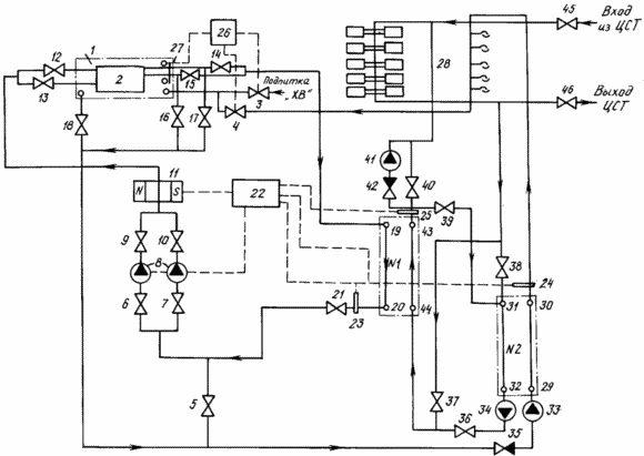
The described construction is presented in the drawing where
1 - tank;
2 - unit of heat generators;
3 - shut-off valve, which opens access to the system of cold water supply;
4 - valves connecting the inverse system of hot water, then - hot water, from entering the tank;
5 - valves connected to the input of the pump group and forming a connection to supply hot water line;
6.7 - fittings, standing at the pump inlet, is connected through pipes with stop valves 5 and 21;
8 - pump included in the pump group;
9, 10 - valves, standing at the outlet of the pump the pump group is connected via a pipeline to the shutoff valves 12, 13;
11 - an electromagnet located on the supply line in front of the heat generator unit 2, located between the shut-off valve 9, 10 and 12-13;
12, 13 - valves, standing in front of the heat generator unit 2 and is connected via a pipe to the shut-off valve 9, 10;
14, 15 - valves, standing at the exit of the heat generator unit 2 connected to the input of the plate heat exchanger 19 №1 (first plate heat exchanger) - hereinafter referred PT №1;
21 - Valves, located at the exit 20 PT №1 and connected by a pipeline system with isolation valves 5,6,7;
22 - unit for monitoring and control of autonomous heating system, related control circuits with temperature sensors 23,24,25 electromagnet 11, motor pump group 8;
23 - temperature sensor located between the output of the TP №1 20 and stop valves 21;
24 - Temperature sensor 30 located downstream of the plate heat exchanger №2 (second plate heat exchanger), hereinafter referred №2 FET;
25 - temperature sensor 43 disposed at the output PT №1;
26 - control unit DHW fed, control circuits associated with isolation valves 3, 4 and adjustable vodoukazatelnym device 27;
27 - adjustable vodoukazatelnoe device embedded into the tank through the piping system and associated control circuits with the block 26;
28 - DHW system users and heating;
29 - the entrance to the plate heat exchanger №2, connected by pipeline to the circulation pump 33;
30 - out of a plate heat exchanger №2, connected to the hot water supply pipe;
31 - the entrance to the plate heat exchanger №2, coupled with isolation valves 38, 39 through the pipeline;
32 - out of a plate heat exchanger №2, connected by pipeline with a circulation pump 34;
33 - circulation pump connected to a pipeline with PT №2 entrance 29 and a check valve 35;
34 - circulation pump connected to the inlet conduit 32 PT №2 and shut-off valve 36;
35 - check valve connected to the circulating pump 33 and shut-off valves 5, 16, 17, 18, piping system;
36 - Valves, located between the circulation pump 34 and the inlet 44 of the heat exchanger plate №1;
37 - valves, connected by a system of pipelines between the stop valve 36 and the inlet 44 PT №1 on the one hand, on the other hand - on the back of the heat supply system;
38 - valves, located on the back of the heating system to PT input №2 31;
39 - valves, connected by piping between the outlet 43 PT №1 and №2 to the PT input 31;
40 - valves, connected by piping between the outlet 43 PT №1 and heat supply system;
41 - Circulation pump heating system, the flow of the heating system after the check valve 42;
42 - check valve disposed between circulation pump 41 and the outlet 43 Fr №1;
43 - exit from the PT №1;
44 - the entrance to the PT №1;
45 - Valves, standing at the entrance of the central heating consumers and the heating system, hereinafter referred DPT;
46 - Valves, standing at the exit of the heat supply system and DPT.
A closed main flow circuit is designed as a system consisting of a heat generator unit 2 is mounted in the tank 1, and associated conduit 14 and stop valves 15 Fr №1, which in turn is connected via conduit 21 with a stop valve in the pump inlet group 8 through stop valves 6 and 7. at the outlet valves 9, 10 installed on the discharge pipe 11. Next, after the solenoid shut-off valve 12, 13 communicates with the input unit 2 in the heat generator installed in the tank 1.
Small closed loop piping system includes mounted thereon and valves 5, 6, 7, 9,10, 12, 13, 16, 17 and the electromagnet 11 connecting with the pump group 8 teplogeneratorov unit 2 mounted in the tank 1.
Circuit between the plate heat exchangers, consisting of a pipe system connecting the output 43 to the input FET №1 №2 FET 31 via stop valves 39, 32 output to the input №2 PT 44 PT №1 through circulation pump 34 and the shut-off valve 36.
DHW is designed as a system consisting of a heat generator unit 2, located in the tank 1. The output from the tank 1 through the shut-off valve 18, check valve 35 and a circulation pump 33 is connected by pipelines to the PT input №2 29. Exit 30 PT №2 associated piping system with hot water supply line 28, then the return line to the tank mounted DHW via pipelines through shut-off valve 4.
Circuit consumer heating system is designed as a system consisting of PT №1, exit 43 which is connected by a pipeline to supply heat supply system 28 through the shut-off valve 40, check valve 42 and a circulation pump 41. The return pipeline heat supply system 28 is connected to the input 31 in PT №2 through shut-off valve 38, the output of the FET 32 connected to the input №2 44 PT №1 through the pipeline system through the circulation pump 34 and the shut-off valve 36 and the return pipe heat supply system 28 is connected to the input 44 in the PT through №1 pipeline system through the shut-off valve 37.
The aim of the invention is to create an autonomous heating system economically and thermodynamically efficient with a block heat sources that are reliable, low consumption of materials that do not require fuel supply (storage, warehousing and so on. D.) And which could be located anywhere (for example, a basement, or ground floor). In addition, autonomous heating system should be automated, easily controlled temperature and pressure coolant and have advanced technological capabilities, in particular able to heat 9 - 10 storey residential building or other amount not less than 30,000 cubic meters. m.
The technical result achieved when using the inventive system is most effectively used several circulation circuits connected to a single autonomous system, where there are
- Main closed circulation loop, which is used with greater thermodynamic and economic efficiency of energy conversion through the use of an electromagnet, but also the use of the least energy-intensive pumps pump group, the use of heat generators of unit disconnected as needed; use of plate heat exchangers, heat removal is efficient, effective hydraulic adjustment of the entire system, the heat transfer coefficient is 3-4 times greater than in kozhuhorubnyh, thanks to a special pleating flowing profile of the plate, which ensures a high degree of turbulence in the coolant flow, as a result - higher efficiency;
- A small closed contour, which is independently used at system startup, when it is working to bring the heat transfer parameters to optimal values;
- Circuit between the plate heat exchangers, which is used for hot water supply in the offseason, when not needed to carry out heating of premises;
- Hot water circuit, which works with more thermodynamic energy conversion effect due to pre-heating of water going for the needs of hot water, and further heating the water to the desired temperature in the high-efficiency plate heat exchanger;
- Consumer loop heating system that operates with maximum thermodynamic efficiency by using two plate heat exchangers, in which the method of rational tying these exchangers together, using two circulation pumps, all of which leads to the greatest thermodynamic effect.
This autonomous heating system differs from the prototype by the presence of five interacting circuit heat-transfer fluid is automatically controlled units for monitoring and control parameters for the three major systems (main closed circulation loop, the hot heating circuit and consumers heating circuit).
System operation begins with the start of operation of small closed loop, through which run the entire system through bringing the heat transfer parameters to optimal values. Fed through the control unit 26 opens valves 3, and is opened and valves 18, 5, 6, 7, 9, 10, 12-15, 21, 16,17, and the tank is filled to the desired value 1, and a small and basic closed circulating coolant circuits. After filling of the tank circuit and coolant (water) comes closing valves 14, 15, 18, 3. From the heat generator 2 installed in tank 1, the coolant is circulated through the pipeline system shut-off valve 5, 6, 7, 9,10, 12 , 13, 16, 17, the electromagnet 11, a pumping group 8 and returns back to block heat generator 2 installed in tank 1.
When the temperature reached 60 ° C activated closed main flow circuit, with the open valves 14 and 15 are closed valves 16, 17 and 5.
The main closed circulation loop operates as follows: the coolant passes through the heat generator unit 1 2, a design feature which reduces the speed and pressure of the coolant, according to the known laws of thermodynamics, changes the mechanical energy of the fluid, which leads to an increase in temperature of the coolant. heat generator unit 2 is immersed in a tank 1 to the upper sealed lid, inside a colored paint with organosilicon t  150 ° C, and isolated from the outside heat-insulating material. The coolant circulates through the pipeline through the shut-off valves 14 and 15, falls on the entrance №1 19 plate heat exchanger, gives off heat the heated environment and through the exit 20 PT №1 by pipeline through the shut-off valve 21, 6, 7, gets to the input of the pumps 8, then through shut-off valve 9, 10, on the pressure pipe on which the electromagnet 11, the line of tension which are directed perpendicular to the movement of the coolant - to increase heat release (so-called "anomalous" heat). Further, through the shut-off valve 12, 13 is returned back to the coolant in the heat generator unit 2 is installed in the tank 1. This circuit is controlled via the control unit 22 according to the signals from the sensor 23.
The circuit between the plate heat exchangers included in the job when you do not need space heating and hot water to consumers is necessary. The circulation of the coolant along the contour between the plate heat exchangers is carried by pipelines connecting output 43 to the input of PT №1 №2 31 PT through the shut-off valve 39, the output 32 to the input of PT №2 №1 PT 44 through the circulation pump 34 and the shut-off valve 36, and the valves 37, 38, 40 is closed. Control of the parameters of the coolant in the circuit monitor and control unit 22 to the sensor readings 23, 24, 25.
DHW serves to heat the water going to the needs of the consumer, which is accumulated in the tank 1, where the heat generators mounted unit 2. The heated water, which goes to the needs of the consumer, is preheated via heat generators wall passes via line 18 through shut-off valve, a check valve 35 and a circulation pump 33 and fed to the input FET 29 №2, heated therein to a predetermined temperature is supplied by flow line 28. Water DHW consumer via a return conduit by hot water through a pipeline shut-off valve 4 is returned back to the tank 1.
serves as the control unit 26 via the water make-up water shutoff valve from the hole 3, the central water supply sources or other sources of water piped directly to the tank 1. When the minimum water level in the tank 1 to the control unit 26 is provided for regulating domestic hot water tank and the automatic replenishment 1 vodoukazatelnogo signal from the controlled device 27, stop valves 3 opens and closes valves 4. When filling the tank 1 to a certain level signal is input to the control unit 26 which commands the closing of valves 3 and 4. The opening of valves for the control parameters in the coolant this circuit unit is carried out monitoring and control 22 to sensor readings 23, 24, 25.
Circuit consumer heating system used to heat consumers involved in the cold period, and can be operated in different modes.
In normal mode, the coolant circulates on a contour of heating consumers, through the circulation pump 34 through line 36 through the shut-off valve reaches the entrance 44 TP №1, where warmed to a predetermined temperature through the exit 43 PT №1 by pipeline through the shut-off valve 40 is supplied to the feed heat supply line 28, where the convective heat giving consumers back on heating feedback line through the shut-off valve 38 to the input of the PT 31 №2, heats the water that goes to the needs of the domestic hot water, through the exit 32 PT №2 to the input of the circulation pump 34. In this case, valves 37, 39 closed, the circulation pump 41 is not running and can be turned on as needed (for more efficient heat transfer in the coldest period).
By lowering the temperature of the outer valve 40 is closed, the coolant through the check valve 42, circulating pump 41 enters the feed line 28, heat supply, where convective heat is giving consumers back on heating feedback line through the shut-off valve 38 to the input of the PT 31 №2, heats the water, extending the needs for domestic hot water, via the outlet 32 supplied to the FET №2 circulation pump inlet 34 via line 36 through shut-off valve 44 reaches the input FET №1, warmed to a predetermined temperature, through the outlet 43 via conduit №1 PT reaches the entrance of the check valve 42. In this case, valves 37, 39 closed.
At night, or for other economic reasons possible closing of valves 36, 38, 39, 40 and the opening of valves 37, off the circulation pumps 33, 34 and the circulation pump 41.
Autonomous heating system operates automatically through the control unit 22. According to the signals of the sensors 23-25 are installed on the main circuits of the system, coming on the electrical circuits in the control unit 22, switch on and off electrical devices included in the system.
CLAIM
Autonomous heating system comprising a main closed circuit, including heat source, stimulus motion coolant driven, expansion tank, feed, reverse and coupling pipes, valves and control valves and an automatic temperature control with a temperature sensor connected chain management to the control unit, wherein that system combined five interconnected loops: the main closed circulation loop, a small closed loop circuit between the plate heat exchangers, hot water circuit - DHW, consumers heating circuit with the main closed circulation loop is designed as a system consisting of a block heat sources installed in the tank, associated pipes and valves in the outlet of the unit heat generator, with the first plate heat exchanger, which in turn is connected through a conduit with shut-off valve facing the outlet of the first plate heat exchanger, the entrance of the pump group by isolating fittings; at the outlet of the pump through a shut-off valve group in discharge pipe mounted electromagnet further through shut-off valve, standing at the entrance to block heat generators, the communication with the entrance of the heat generator unit installed in the tub; small closed loop system composed of piping and installed thereon solenoid valves and connecting the pumping unit with a group of heat generators, installed in the tub; circuit between the plate heat exchanger consists of a system of pipelines connecting the output of the first plate heat exchanger to the input of the second plate heat exchanger via shut-off valve, the output of the second plate heat exchanger - to the input of the first plate heat exchanger through a circulating pump and the shut-off valve; DHW is designed as a system consisting of a heat generator unit located in the tank, out of the tank through the shut-off valve, check valve and the circulation pump is connected by pipelines to the input of the second plate heat exchanger, the second plate heat exchanger outlet piping is connected with the supply hot water consumer systems line inverse DHW line via pipelines through shut-off valve is connected to the input of the tank; Consumers heating circuit is designed as a system consisting of the first plate heat exchanger, the output of which through conduits associated with the supply of heat supply system via a shut-off valve, check valve and pump, wherein the return heat supply system piping is connected to an input of the second plate heat exchanger via shut-off valve, the output of the second plate heat exchanger is connected to the input of the first plate heat exchanger through the pipeline system through the circulation pump and the shut-off valve, a return of heat supply pipeline system is connected to the input of the first plate heat exchanger through the pipeline system through a shut-off valve; block heat generators, installed in the tank, termomaterialami isolated from the external environment; unit pumps connected in parallel; flow control and management of the entire autonomous heating system connected to the control circuits of temperature sensors attached to the three systems - the main closed loop circuit, DHW and heating circuit pumps and motors consumers electromagnet; DHW fed a control unit connected to the control circuits isolation valves, standing on the cold water supply line and return hot water pipe and adjustable vodoukazatelnym device, built-in tank unit with heat generators.
print version
Publication date 07.12.2006gg


Comments
Commenting, keep in mind that the content and the tone of your messages can hurt the feelings of real people, show respect and tolerance to his interlocutors, even if you do not share their opinion, your behavior in terms of freedom of speech and anonymity offered by the Internet, is changing not only virtual, but real world. All comments are hidden from the index, spam control.