| section Home
Production, Amateur Radio amateur Model aircraft, rocket- Useful, entertaining |
Stealth master
Electronics Physics Technologies invention |
space Mystery
Earth Mysteries Secrets of the Ocean Stealth section Map |
  |
| Use of material is permitted for reference (for websites - hyperlinks) | |||
Navigation: => |
Home / Forum Index / Contents sub / |
|
Crank mechanism WITHOUT CRANKSHAFT
MECHANISM FOR TRANSFORMATION rectilinear motion into rotary and vice versa
Muschinsky Anatoly Klimentievich
Imagine the situation. Are you traveling in the desert, in the forest, where there are no repair shops and engine of your car banged crankshaft.
Can you replace yourself in the desert, the crankshaft in a modern engine?
Of course not.
Crank mechanism proposed design type manufactured modular and allows replacing modules under all conditions, without removing the engine.
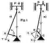
A significant disadvantage of ICE (internal combustion engine), it is a crank (crank mechanism). Over the entire period of the internal combustion engine, perfected the technology of manufacturing crank and its individual components, however, the traditional crank design does not allow to increase the efficiency of the crank above 40%. This is due to the fact that when the crank angle between the crank and the connecting rod varies from 0 to 360 degrees. The upper and lower dead points of its efficiency = 0, and the points at which the angle between the connecting rod and crank = 90 degrees, Fig.1a, its efficiency = 100%. In all other points there is a decomposition of forces Fig.1v, which reduces its efficiency. As a result, its average efficiency of less than 40%.
|
Increase efficiency crank is only possible by reducing the decomposition of forces. Approaching an unconventional method of building construction crank, I have achieved the desired result. The difference is that instead of the crankshaft applies a simple shaft with gears on each rod, the internal combustion engine without changing the overall design. Each rod cooperates with the shaft through the planetary gear. The design greatly reduces the expansion force and a longer period of time for one cycle of the piston, the angle of 90 degrees is stored as the crank increases up to 95% efficiency.
Lack crankshaft significantly reduces the volume of the engine and complexity of manufacturing it. |
For stable and efficient work of construction is used to stabilize.
Eventually:
- KPD is increased by 60% from the conventional KSHM, chart "D" and "C";
- Lack crankshaft simplifies and cheapens the entire crank design as in the manufacture and maintenance;
- Increases engine service life and the continuity of the internal combustion engine;
- Simplified system crank lubrication. The proposed design of self-lubricating;
- When using the proposed crank, cylinder arrangement may be any different in the plane, as well as the internal combustion engine can be manufactured modular type;
- The design is simple. It uses the details for a long time used in mechanics, and neither should be on this large additional research.
The invention relates to the mechanisms used in both industrial and household nodes mechanisms and units where necessary converting translational movement into rotational and vice versa. For example: internal combustion engines - crank mechanism; in the oil industry, for lifting and lowering the rod pump, etc.
This structure simultaneously performs two functions:
- Conversion of translational movement into a rotary and vice versa;
- reducer function with a wide range of gear ratios.
The diagram "D" was drawn up at a constant power of "P" acting on the piston.
The measurements were carried out experimental and practical way on the current layout.
Explanatory table "D" shows the efficacies of the conventional and the proposed crank at a permanent force "P" on the piston.
However, when the engine is running, the power of "P" varies. When moving the piston downward, the combustion chamber volume increases, the gas pressure is reduced by that lowers the engine output. This diagram illustrates the "A" (the shaded portion in gray).
In the conventional design of crank small efficiency due to the large expansion of forces, which clearly illustrates the diagram "B".
Diagram "C" illustrates the efficiency of the proposed design of crank mechanism (the shaded portion in gray).

Below is an explanatory table "D".
Explanatory table was compiled on the basis of experimentally - practical impact measurement constant force "P" on the piston.
The first column shows the rotation in degrees of the crankshaft.
The second column displays the changing pressure Cily "P" on the piston during engine operation. This column is enabled for the overall presentation of the changes in the Force "P" during engine operation.
The third column shows the efficiency of a conventional crank at a constant pressure on the piston Cile "P" in the measurement period.
The fourth column shows the efficiency of the proposed crank at constant pressure on the piston Cile "P" in the measurement period.


There is a working model showing all above stated.
This invention is patented.
print version
Author: Anatoly Muschinsky Klimentievich
PS material is protected.
Publication date 12.02.2005gg
![]()

Comments
Commenting, keep in mind that the content and the tone of your messages can hurt the feelings of real people, show respect and tolerance to his interlocutors, even if you do not share their opinion, your behavior in terms of freedom of speech and anonymity offered by the Internet, is changing not only virtual, but real world. All comments are hidden from the index, spam control.