
| Start of section
Production, amateur Radio amateurs Aircraft model, rocket-model Useful, entertaining |
Stealth Master
Electronics Physics Technologies Inventions |
Secrets of the cosmos
Secrets of the Earth Secrets of the Ocean Tricks Map of section |
  |
| Use of the site materials is allowed subject to the link (for websites - hyperlinks) | |||
Navigation: => |
Home / Table of Contents / Table of Contents / |
|
METHODS AND DEVICES OF RADICAL FUEL ECONOMY
IN THERMAL ENGINES OF TRANSPORT AND IN HEAT-POWER ENGINEERING
AND SIMULTANEOUS RADICAL IMPROVEMENT OF THEIR ECOLOGY
![]()
Dudyshev Valery Dmitrievich, Russia, Samara
Samara Technical University
ESSAY
It is known that world heat and power engineering and transport are the main world consumers of fuel and the atmosphere of the planet, and, at the same time, the main environmental pollutants of the atmosphere and the entire environment. Therefore, radical energy conservation in these most important sectors is most significant for the sustainable development of civilization for the foreseeable future. The article is devoted precisely to the search for ways of radical energy saving by reducing the consumption of fuel consumed by energy and transport. More specifically, it is devoted to the search, analysis and justification of efficient technologies, methods and devices for radical fuel economy in transport and in heat and power engineering. The general methodological principle of solving the problem of radical fuel saving by the author of this problem is a systemic campaign in accordance with which the processes of preparation, activation and efficient, environmentally friendly burning of fuels, water-fuel emulsions and various fuel-air mixtures are interdependent and, therefore, must be considered and solved in a complex. Many of the new technical solutions proposed in the article for significant fuel economy, and more broadly, in the field of new energy-saving technologies, are patented, tested and investigated. These new energy-saving technologies, in the opinion of the author, in case of their mass introduction, will significantly reduce the severity of the global energy and environmental problems of civilization. The article is well illustrated and contains a fairly extensive bibliography of articles and inventions of the author on this topic. The editorial board hopes that this article will arouse keen interest to a wide audience of readers, and it will be useful to specialists - energy specialists and environmentalists.
SETTING THE PROBLEM AND SELECTING THE METHOD OF ITS SOLUTIONS
Fuel and energy are constantly becoming more expensive, so the methods for their savings are very relevant.
The global interconnected environmental and energy problem of civilization is a harsh objective reality of our time, a convincing proof of the imperfection of its technologies and a real threat to the sustainable development of modern civilization. Are there any effective ways to solve it? Yes there is! There are only two main ways to solve this problem. The first main path of the Power Industry is to learn how to produce a lot of clean cheap energy and the second way is to economically spend the generated useful energy .. It is quite clear that the first way is more difficult.
Therefore, at the first stage of the development of the World Energy Sector in order to solve the global energy problem, it is necessary to create and everywhere introduce alternative energy-saving technologies for the economical production and consumption of fuel, heat and electricity. At the second stage, it is necessary to create generally non-fuel alternative energy. However, in reality both of these areas of development of alternative energy are developing simultaneously. For example, I have previously proposed new efficient sources of thermal and electric energy, with anomalous energy ,. In particular, electrohydrocavitational heat generators, non-contact magnetoelectric generators on ring permanent magnets, new low-cost electrohydrodynamic power, in particular electrohydraulic shock turbo-electric generators, electric-water motors and much more. For the development and development of alternative energy / 4-8 / . However, for the radical fuel-energy saving, I have already been offered earlier, and a number of new energy-fuel-saving technologies / 1-4-, 9-27./ have been thoroughly substantiated, developed, tested, and. In particular, a new effective electric fire technology for environmentally friendly intensive combustion of any fuels and wastes was developed and introduced / 1-3 / . It is applicable, in fact, in all firing processes without exception, and is based on the fundamental discovery of the author of the powerful catalytic effect of electric fields on the combustion of any substances / 1-3 / . This unique in its effectiveness technology allows you to burn not only different fuels. But also usefully use any organic waste as fuel. The electric field and capillaries were earlier and successfully used by the author in the unique low-cost electroosmotic H2- technology for cold evaporation and electro-radiolytic dissociation for water and any aqueous solutions of fuel gases / 26,27 / . This progressive electric fire technology in combination with other technologies of useful use of electric and magnetic fields offered in the article makes it possible to save from 20 to 80% of the main fuel in complex use. And so the proposed technologies can now successfully be used in heat and power engineering and transport, bringing tangible economic benefits to their owners. The technologies are implemented in practice in the form of fairly simple and effective radical fuel-energy saving devices, described below.
COMBINED METHOD OF MAGNEELECTRIC
ACTIVATION OF FUEL, OXIDATOR AND FLAME BURNING PROCESS
In order to radically save fuel it is necessary to achieve its effective combustion and any heat and power plant. In order to completely and environmentally clean fuel - it is necessary to prepare it in the beginning, and the oxidant too, and then also to combine them qualitatively and homogenize, and even efficiently ignite this fuel mixture. Below, new methods and devices for the intensification of all these stages are considered, including:
- Simultaneous filtration and magnetoelectric fuel activation
- Simultaneous electroactivation and filtration of oxidant
- Fine electrostatic spraying of fuel
- Activation of the ignition of the fuel mixture (plasmatron with rotation of the electric arc)
- Vortex mixing of fuel mixture components
- Electrofield activation of combustion of any fuel mixture in a flare
Let us consider in more detail these methods of reducing fuel consumption and improving the ecology of its combustion.
MAGNETOELECTRIC ACTIVATION OF FUEL
The technology is designed to increase the fuel efficiency of ICE and any fuel burners by introducing effective fuel activators into the fuel path. To realize this useful innovation, it is advisable to combine the design of the fuel filter and the fuel activator. For this, the capacity of the fuel filter is converted into an unusual high-voltage electric capacitor with a liquid dielectric, Fuel, and as one of the plates of which is the outer housing of the fuel filter. Moreover, the fuel filter is additionally provided with a source of magnetic field located in this fuel filter and an electric field source with a voltage of 10-20 kV and two electrodes, one of which is made In the form of an electrically conductive hollow electrode serving as a fuel inlet or as a volumetric electrically conductive filter element and is housed inside a fuel tank and the other electrode is in the form of an annular electrically conductive element and is located outside the dielectric capacitance of the fuel filter, and the outputs of these electrodes are electrically connected To the source of the electric field. Figure 1 shows a block diagram of the fuel filter .. activator.
The fuel filter activator ( Fig. 1 ) consists of a dielectric capacitance 1 with an inlet 2 and an output 3 fuel nozzles, an electric field source 4 electrically connected to the electrodes 6 and 7 , and the electrode 6 is coaxially located inside the dielectric capacitance 1 and is made in the form of a rod On which an electrically conductive filter element 8 made of, for example, a hydrocarbon fiber is installed to provide electrical contact, and the electrode 7 is mounted outside the dielectric container 1 with the ability to move along the cylinder of the housing 1 . Outside the dielectric capacitance 1 , at least one magnetic field source 8 , for example, an annular permanent magnet 9 , is installed.
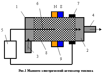
The fuel filter activator works as follows.
Fuel 2 from the fuel tank and through the supercharger (not shown in Fig. 1 ) and through the inlet branch pipe 3 enters the dielectric capacitance 1 . It is an unusual electrical capacitor whose first cover is an electrically conductive electrode 6 and a volumetric electroconductive filter 8 on one side and a remote annular electrode 7 , on the other hand, separated by a dielectric material of the housing.
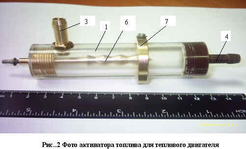
The electrodes 6,7 are connected to the outputs of the source of the electric field 5 . Fuel 2 enters the inlet pipe 3 and through the outlet pipe 4 into the power supply system of the power plant (not shown in Fig. 1 ). The fuel 2 in the tank 1 is simultaneously cleaned of impurities and activated by an electric field from the source 5 and a magnetic field from the magnet 9 when passing through the active filter element 8 , which simultaneously is a volumetric electrode - and provides electronic emission into the fuel. As a result of the structural combination of the filter element and the activator electrode, the fuel undergoes simultaneous fine cleaning from foreign mechanical parts and efficient magnetoelectric activation, at an atomic-molecular level providing a high degree of its electrochemical activity and increasing its energy caloric content, which ensures a high degree of combustion of the activated fuel In the heat and power plant, fuel economy at the level of 20-30% and obtaining high environmental parameters of the exhaust gases from the combustion zone. The invention is recommended for wide application in transport, in engine building and in any other fire technologies, for example, in boiler plants. In Fig. 2 shows the photo of the fuel electroactivator (bso removed by a magnet and without a filter material).
The performed calculations, experiments and comprehensive studies of various modifications of hybrid fuel activator and oxidizer filters convincingly demonstrate their efficiency, achieved with proper design and manufacturing in relation to a given task - and a specific heat energy facility (boiler plant and so on). Experiments showed that with the optimal ratio of constructive and other parameters, the filter-activator of fuel allows to save up to 20-30% of fuel and allows using lower-grade fuel grades and depleted and ballasted water and steam fuel while maintaining its previous calorific value. At the same time, due to the complete combustion of fuels, carbon deposits on the nozzles and boilers are eliminated, which increases their reliability and improves the ecology of combustion.
STEAM - IT'S FUEL AND DRIVING FORCE AND EFFECTIVE CLEANER OF AUTOMOBILE
For a long time successful experiments on ballasting of fuel by water and steam and its combustion in heat power engineering and on motor transport have been known. Water-fuel emulsions and fuel-fired aerosols are quite applicable both in automotors and in boiler-houses and allow to save substantially the main fuel. However, there are still many finds and technical solutions in this way. With the introduction into the burners and in the automotors of the original ignitors-simple plasmatrons with rotation of the electric arc There is a unique technical opportunity to even more bankroll the main fuel with water (up to 50-60% ) and successfully and cleanly burn it, for example in an electric field.
The device for supplying moist air or steam to the suction header of the heat engine or through the burner in the boiler room is very attractive not only for saving fuel but for removing carbon deposits in the combustion chambers and from the boiler and, when igniting efficiently, leads to an improvement in the combustion of the fuel, Dissociates in the flame to H2 and O2 , especially with simultaneous electrification of water vapor and the flame itself. Let us now compare fuel and water costs, like air moisture, in automotive thermal engines with conventional combustion. From the stoichiometric ratio of 1:15 , it follows that fuel is consumed approximately 7% by weight of the required air flow. But moisture in the air is from 1 to 2% , and taking into account the coefficient of excess air - up to 5 ... 6% . That is, the engine consumes about the same amount of moisture as the fuel. That is why a moisture deficit, as an electron donor, along with fuel, makes it difficult to start the engine in winter. From the experience illuminated in the technical literature, it is known that the addition to the fuel-air mixture of water improves the combustion process and reduces fuel consumption by up to 30% . In addition, the preparation of a good mixture of 50% fuel and 50% water, connected at the molecular level in the form of non-exfoliating emulsion, gives the same effect on the calorific value of fuel as pure gasoline. This fact confirms the identity of the work of moisture and fuel in the fuel mixture, and it is exactly equal.
There is another, as already mentioned above, an important positive effect from the introduction of steam into the motor .. The fact is that when water vapor interacts with carbon at a temperature above 750 degrees, it decomposes into constituents. So, the product of incomplete combustion of low-grade fuels - carbon black - water vapor accumulated in combustion chambers actively decomposes during a flash and high-temperature combustion of the steam-fuel mixture in the cylinders of the thermal motor. Who does not know this - they constantly argue that the steam is nothing sensible to the transport engine does not. However, the engine that uses steam is always clean! Because the steam with the benefit of processing all the soot. In fuel synthesis gas. In our experiments on an internal combustion engine with the addition of steam with some cheap hydrocarbon additives, it achieved the economy of the main fuel, up to 40-50% . This radical fuel economy has been achieved with an environmental cleanliness of exhaust gas at Euro 3, 4 . But this is not the limit and there is a real possibility of motors and burners working on only one water vapor / 1 / Especially this complete combustion of this fuel mixture is facilitated by electrostatic spraying of ballasted water with fuel. About this below.
ELECTROSTATIC SPRAYING OF WATER-FUEL EMULSIONS
The electric field can provide Coulomb forces of repulsion and fragmentation of droplets ideal atomization of fuel in nozzles with minimal energy consumption. In combination with vortex mixing of fuel mixture components with oxidizer, this will lead to the best homogenization of the fuel mixture and,. As a result, deep combustion of fuel and significant fuel economy.
Figure 3 shows the device for electrostatic atomization of a fuel mixture using the example of an internal combustion engine of an engine.
The fuel mixture preparation apparatus consists of a fuel tank (not shown), a high-pressure fuel pump 1 connected via a fuel line 2 to a fuel injector 3 (engine injector). It is simplified and consists of a body 4 having a fuel channel 5 and a nozzle 6 . At the nozzle 3, an annular electrically insulating insert 7 is placed, and an annular electroconductive electrode 8 with an inner diameter of the hole larger than the diameter of the nozzle 6 is fixed thereto. The device includes a vortex mixer 9 having tangential insertion into the mixer, for example in the form of one or more openings in the housing (only one opening is shown), for intensive vortex mixing of the fuel-air mixture components, namely atmospheric air, exhaust hot engine gases, steam , Inside this vortex mixer 9 , with their subsequent feeding tangentially into the conical branch pipe 11 , into the zone of vortex twist of the main oxidizer-air flow. The vortex mixer 9 is connected by a conical branch pipe 11 to the inlet 13 of the working cylinder of the combustion chamber 14 of the engine, shown in a simplified manner. In the combustion chamber 14 of the engine, there is a standard electric spark plug 15 comprising a central electrode 16 , an electrical insulator 17 and a housing 18 with a screw-in part and a side electrode 19 electrically connected to the engine mass. Electrodes 16 , 19 of the spark plug and electrodes 8 , 16 of the electrostatic fuel atomizer are respectively connected to the sources 20 and 21 of the constant high voltage pulse voltage to the power source, for example, to the battery 22 . In the drawing, the engine exhaust manifold 23 , the electrostatic spraying zone of the fuel 24 , the zones of intensive vortex mixing of fuel and oxidant 26 , fuel components 25 and ignition are simplified. The device works as follows.
When the fuel is injected into the fuel injector 3 and high voltage voltage pulses to the ring electrode 9 synchronized with the fuel ignition pulses on the spark plug 15 , the fuel from the nozzle cutoff 8 is finely and intensely sprayed by the Coulomb repulsive forces due to electric charging of the fuel jet with an electric charge of the same name, and simultaneously activated In an electrostatic field. At the same time, intensive vortex mixing of fuel mixture components takes place in the vortex mixer 9 of the fuel atomization zone. The air coming from the air filter into the conical swirler 11 of the vortex mixer 9 is intensively twisted simultaneously in the vortex nozzle 1 located in the inlet branch pipe 8 and fixed by the gasket 9 , then the swirling air in the mixing zone 23 is intensively mixed with the fuel sprayed by the injector nozzle 3 , And then, through the conical nozzles 11 , 12, an activated, well-mixed FA is introduced into the combustion chamber 14 of the engine cylinder, via the inlet port 13, with the intake valve raised (not shown), namely the concentration and ignition zone of the fuel assembly 26 , since a second electrode Potential from the block 20 , which is unlike with respect to the electrical potential, which is charged with fuel at the nozzle section 8 .
Due to the thin atomization of fuel by electric field and vortex mixing of fuel assemblies, the quality of fuel assemblies in zone 25 is much higher than in analog.
As a result, an increased degree of dispersity of the fuel atomization, homogeneity of the fuel mixture is achieved, and its combustion is increased, i. E. The ecology of ICE and the fuel efficiency of ICE and other burners are significantly improved.
METHOD OF ROTATION OF ELECTRIC ARC FOR INTENSIVE IGNITION AND COMBUSTION
ANY ON THE COMPOSITION OF THE FUEL MIXTURE - AS AN EFFECTIVE WAY OF REDUCING FUEL CONSUMPTION
IN ENERGY AND TRANSPORT
| Http://WWW.SHRAM.KIEV.UA/techno/techno2_3/8.shtml | Http://WWW.SHRAM.KIEV.UA/techno/techno2_3/9.shtml |
This section of the article is devoted to the description of a new technology - including the method and devices of intensive ignition and combustion of any fuel-air mixture, for example, significantly depleted, prepared from low-grade fuel by means of an original simple plasmatron with a rotating electric arc and its spheres of useful use in burners and fuel igniters. From heat and power to all modes of transport. While practically all ignition devices for burners and internal combustion engines use conventional electric spark methods and devices. However, they do not allow to ensure effective ignition and combustion of fuel, and as a result lead to over-consumption of fuel and increased toxicity of the off-gases. Is there an exit? Yes there is - you need to ignite the fuel mixture rotating electric arc! Consider this innovation and the options for its implementation and application in practice in more detail.
EFFECTIVE MAGNETIC FIRE OF THE IGNITION WITH THE ROTATION OF THE ELECTRIC ARC
While electric spark plugs - are quite imperfect in gasoline cars, including injectors - and in many respects they are responsible for the gluttony of gasoline cars of ICE and their low ecology. Because the fuel mixture ( fuel assembly ) does not have time to effectively ignite and burn in the cylinders of the engine for short intervals of the working stroke of the engine. I propose a much more effective spark plug, which will increase the completeness of combustion fuel fuel , even if it is depleted or re-enriched. To radically improve the standard spark plug, it is necessary to make very little transition from a single electrical discharge to a circular plasma spot of rotating electrical sparks. In this case, the fuel mixture will ignite much faster and more efficiently, which means it will burn better, which leads to the economy of the engine and the ideal environmental cleanliness of exhaust gases with a level of toxicity at least within the limits of Euro 3-4 norms without an external neutralizer of the VG DVS. And eliminating the external neutralizer VG - immediately give a fuel economy of at least 10-15% .

MODERNIZATION OF THE CONSTRUCTION OF THE STAINLESS STEERING CANDLE LIGHT
To do this, it is necessary to significantly improve the operational properties of a known standard electric spark, namely to ensure the rotation of the electric arc in it in the working intervals of its operation. And for this you just need to change its design a bit - a conventional spark plug for automotive ICEs, adding to its design some simple changes, namely:
- Eliminate the lateral mass electrode and replace it with a ring electrode, which is already practically there in the design of this candle.
- Place in a standard spark plug a small annular permanent magnet (design, KNOW HOW ).
- Increase the time of high voltage supply to the spark plug ( KNOW HOW ).
This technical result is achieved by introducing a magnetic field source in the form of an electromagnet or permanent magnet placed in such a way that magnetic lines of force intersect the working gap between the electrodes in a known device, an electric spark plug containing a metal casing and electrodes separated by an insulator A combustion chamber, for example, an electromagnet or a permanent magnet is mounted on the outer part of the insulator of the body of the magnetoelectric spark plug, and the central electrode is a magnetic circuit that closes the magnetic lines of force in the working gap of the magnetoelectric spark plug inside the combustion chamber, which leads to the formation between the central and ring electrodes of a rotating electric arc Ignition of the magnetic dipole of the annular permanent magnet 6, closing its magnetic poles between the annular electrode 5 and the central electrode 2, where an electrical discharge occurs in the form of a rotating electric spark 9 of ignition, and the end electrode 10 is added to the central electrode, a diameter exceeding the diameter of the central electrode 2 , for Increase its service life.
Magnetic spark plug with electric arc rotation
In Fig. 4, 5, in two projections, an original magnetoelectric spark plug is shown, comprising a metal casing 1 , a central electrode 2 with an electrical insulator 3, a side post 4 with an annular electrode 5 , eg in one plane with a central electrode and an inner diameter providing an electric arc, A permanent magnet 6 coaxially located from the outer part of the spark plug insulator 3, a combustion chamber 7 of the internal combustion engine, magnetic field lines 8 .
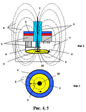
The magneto-electric spark plug works as follows. High voltage pulses are applied to the central electrode 2 from the ignition coil (not shown in the figure). The source of the magnetic field 6 , for example, an annular permanent magnet 6, creates in the spark plug a magnetic field of a dipole type of a given intensity. The magnetic lines of force 8 of the permanent magnet 6 are closed through the central electrode 2 , the electric arc 9 , the ring electrode 5 and the housing 1 . Due to the intersection of the electric arc 9 by the magnetic power lines 8 , the latter comes into rotation as a result of the force interaction of the magnetic field of the annular permanent magnet 6 with the electric current flowing in the electric spark 9 between the central electrode 2 and the ring electrode 5 . The regulation of the speed of rotation of the electric arc is provided by changing the magnitude of the electric current in arc 9 and the value of the magnetic induction from the permanent magnet 6 . The reverse rotation of the electric arc is provided by rotating the permanent ring magnet 180 degrees. In the case of using an electromagnet, the reversal of rotation of the electric arc 9 is performed by changing the polarity of the voltage on its winding. Due to the rotation of the electric arc along the ring electrode 5, the wear of the latter is minimal. To reduce the wear of the central electrode, its end is made in the form of a disk 10 . As a result of the rotation of the electric arc 9 between the annular electrode 5 and the central electrode 2 . A plasma spot is formed. As a result, the intensity of ignition of the fuel-air mixture in the combustion chamber 7 increases, which leads to improved combustion, and as a consequence, to a reduction in fuel consumption and to improving the environmental purity of the exhaust gases of the internal combustion engine. Additional positive effects of such a spark plug are the effective start of the cold engine, the possibility of the engine running on depleted fuel mixtures, and in improving its reliability and service life.
EXPECTED TECHNICAL INDEXES FROM APPLICATION
MAGNETIC IGNITION CANDLE WITH ELECTRIC ARC ROTATION IN ICE
- Expected fuel economy DVS - 15-20% .
- Increase the acceleration of the gasoline engine.
- Absence of deposit.
- Reducing wear of candle electrodes.
- Increase of reliability in work.
- Simplify the adjustment of the ignition angle.
- Multiple reduction in toxicity of exhaust gases, i.e. Dramatic improvement in the ecology of the car.
- The possibility of reliable operation on lean fuel mixtures and low-grade gasoline.
TECHNICAL ADVANTAGES OF THE MAGNETIC IGNITION CANDLE
A new, more efficient, magnetic spark plug for ICE will help save fuel because it will better ignite the fuel mixture in the engine's cylinders. The electric arc in this modernized spark plug with a permanent magnet does rotate, and at a transonic speed, which is confirmed by my laboratory experiments of the past. In addition, in such an unusual magnetic spark plug, it is possible to control the rotation speed, duration and power of the plasma spot. Magnetoelectric spark plug with rotating electric arc for internal combustion engines.
The invention relates to internal combustion engines, and can be used in gas turbine engines and in fuel ignition systems in any burners in which a fuel mixture is ignited by electric spark plugs. The closest device of the same designation to the claimed utility model for the totality of features is an electric spark plug for internal combustion engines containing a metal casing and electrodes separated by an insulator (prototype is RF patent 2239925 ). With all the advantages of the prototype, the existing electric spark plug fuel-air mixture has a reduced reliability due to the phenomenon of carbon deposits, reduced fuel efficiency and reduced efficiency due to the impossibility of ignition of depleted fuel mixtures and as a result resulting in incomplete combustion of the fuel-air mixture, And high toxicity of exhaust gases. The technical result of this utility model is to obtain the effect of rotation of the electric arc in the presence of a source of a magnetic field in the spark plug, for example a permanent magnet, and in the formation of a traveling concentric arc of ignition between the central and ring electrodes, leading to a reduction in the combustion time of the fuel-air mixture in the combustion chamber . As a result, the intensity of ignition of the fuel-air mixture in the combustion chamber increases, which leads to improved combustion, and as a result, to lower fuel consumption and improve the environmental cleanliness of the exhaust gases of the internal combustion engine. Additional positive effects of such a spark plug are the effective start of the cold engine, the possibility of the engine running on depleted fuel mixtures, and in improving its reliability and service life. It is quite obvious that this original useful novelty for motorists and their favorite cars is at the same time a profitable commercial offer for potential investors, because this new effective spark plug can become, thanks to its unique properties, a revolutionary step in engine development, significantly improve the operational properties of engines Internal combustion, up to transferring them to cheaper fuels while maintaining performance and up to eliminating the expensive and unreliable external device for catalytic exhaust gas purification, which reduces the power of the internal combustion engine and leads to a fuel overexpenditure of 15% . As a result of elimination of the output cellular neutralizer and the operation of the ICE with lean fuel mixtures with this method of igniting the mixture, the total fuel economy in modern ICE vehicles with the introduction of such magnetic spark plugs can reach 20-30% with such spark plugs. Well, how do you like this prospect? Therefore, the proposed effective and rather simple magnetic candle will probably be a very demanded and useful commodity of wide demand, and can be fully installed not only on second-hand cars, but also on conveyors of car factories during the serial assembly of motor vehicles, since it will provide the gasoline engine with new useful performance properties, in particular Will improve their acceleration and economy, reliable start-up in the winter season, and uncriticality to the ambient temperature and will ensure, importantly, a high degree of purity of the exhaust gases in general without an external neutralizer of exhaust toxicity.
Объем рынка ее сбыта- огромен –это миллиарды штук- такое количество бензиновых ДВС в мире т.е. рынок сбыта магнитных свечей зажигания – это практически весь парк автомобилей с топливом в виде бензина и газа- а территория охвата – это весь земной шарик.
Конструкцию оригинальной магнитной свечи зажигания в промышленном исполнении имеет некоторые простые НОУ-ХАУ . Кстати, эта уникальная свеча зажигания может найти применение и в авиационных двигателях и в вертолетах и много еще где она тоже вполне пригодиться и повысит топливную экономичность и надежность работы авиационных газотурбинных и поршневых двигателей на 20-30% .
ЭКОНОМИЧНАЯ МАГНИТНАЯ ТОПЛИВНАЯ ГОРЕЛКА ДУДЫШЕВА С ВРАЩАЮЩЕЙСЯ ЭЛЕКТРОДУГОЙ
Изобретение относится к горелкам для энергетических котлов, газотурбинных и парогазовых установок и любых топок промышленных печей. Наиболее близким устройством того же назначения к заявленной полезной модели по совокупности признаков относится горелка для сжигания топлива, содержащая корпус, топливопровод, соединённый с форсункой. При всех достоинствах, существующая горелка не могут обепечить радикальную экономию топлива, обладает пониженной надёжностью из-за явления нагара, пониженной топливной экономичностью и пониженным КПД в связи с невозможностью воспламенения обеднённых топливных смесей и как следствие приводящее к неполному сгоранию топливной смеси, перерасходу топлива и высокой токсичности выхлопных газов. Технический результат данной полезной модели состоит в том, что она дополнительно снабжена электрическим изолятором, размещённым в корпусе горелки снаружи топливопровода и форсунки и получении эффекта вращения электрической дуги при наличии в горелке источника постоянного магнитного поля, например, постоянного электромагнита или постоянного магнита и в образовании между соплом форсунки топливопровода и коническим диффузором корпуса горелки бегущей концентричной дуги зажигания, приводящей к повышению интенсивности воспламенения и горения топливной смеси, и как следствие, к снижению расхода топлива и улучшению экологической чистоты отходящих газов. Дополнительные положительные эффекты такой универсальной горелки состоят в её эффективном запуске и возможности работы горелки на обеднённых топливных смесях, а и в повышении её надёжности и срока эксплуатации.
Указанный технический результат достигается тем, что в известное устройство горелки, содержащей корпус, топливопровод, соединённый с форсункой, дополнительно введен электрический изолятор, размещённый в корпусе горелки снаружи топливопровода и форсунки, источник постоянного магнитного поля, выполненный в виде постоянного электромагнита или постоянного магнита, размещённого таким образом, чтобы магнитные силовые линии источника магнитного поля пересекали рабочий зазор между выходным соплом форсунки и коническим диффузором корпуса горелки, например, постоянный электромагнит или постоянный магнит установлен на внешней части корпуса горелки, причём топливопровод горелки является магнитопроводом замыкающим магнитные силовые линии в указанном выше рабочем зазоре горелки, что приводит к образованию между выходным соплом форсунки и коническим диффузором корпусом горелки вращающейся электрической дуги - плазмы.
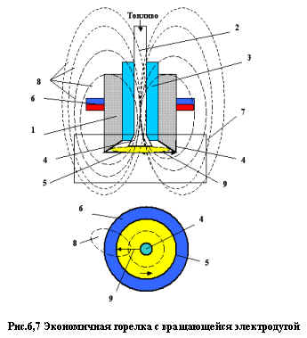
In Fig. 6, 7 показана в двух проекциях универсальная горелка с вращением электрической дуги, содержащая металлический корпус 1 , топливопровод 2 с электроизолятором 3 , сопло форсунки 4 топливопровода 2 , конический диффузор 5 корпуса 1, кольцевой постоянный магнит 6 , коаксиально размещённый с наружной части корпуса 1 горелки, камеру сгорания 7 , магнитные силовые линии 8 магнитного диполя кольцевого постоянного магнита 6 , замыкающие его магнитные полюса между коническим диффузором 5 корпуса 1 горелки и соплом форсункой 4 топливопровода 2 , где и происходит электрический разряд в виде вращающейся электрической дуги 9 .
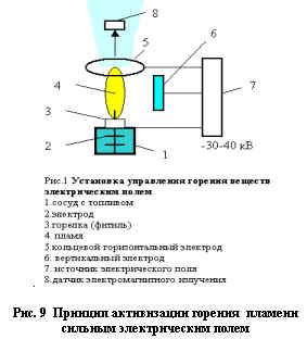
ПРИНЦИП РАБОТЫ УНИВЕРСАЛЬНОЙ МАГНИТНОЙ ТОПЛИВНОЙ ГОРЕЛКИ
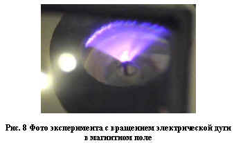
На топливопровод 2 горелки от источника высокого напряжения (на рис. не показан) подаётся регулируемый знакопостоянный электрический ток. Источник магнитного поля 6 , например, кольцевой постоянный магнит 6 создаёт в свече зажигания магнитное поле дипольного типа заданной напряжённости. Магнитные силовые линии 8 постоянного магнита 6 замыкаются через топливопровод 2 , сопло форсунки 4 , электрическую дугу 9 , конический диффузор 5 корпуса 1 . Вследствие пересечения магнитными силовыми линиями 8 электрической дуги 9 , последняя приходит во вращение в результате силового взаимодействия магнитного поля кольцевого постоянного магнита 6 с электрическим током, протекающим в электрической искре 9 между соплом форсунки 4 топливопровода 2 и коническим диффузором 5 корпуса 1 . Регулирование скорости вращения электрической дуги обеспечивают изменением параметров электрического тока в дуге 9 и величиной магнитной индукции от постоянного магнита 6 . Реверс вращения электрической дуги обеспечивается посредством поворота постоянного кольцевого магнита на 180 градусов. В случае применения постоянного электромагнита реверс вращения электрической дуги 9 осуществляют изменением полярности напряжения на его обмотке. Вследствие вращения электрической дуги в промежутке между коническим диффузором 5 корпуса 1 и соплом форсунки 4 топливолпровода 2 образуется плазменное пятно. В результате повышается интенсивность воспламенения и улучшению горения топливной смеси в камере сгорания 7 , и как следствие, к снижению расхода топлива и улучшению экологической чистоты отходящих газов Дополнительные положительные эффекты такой универсальной горелки состоят в её эффективном запуске при розжиге горелки, возможности работы горелки на обеднённых топливных смесях, а и в повышении её надёжности и срока эксплуатации. На рис.8 показана фото опыта с вращением электрической дуги в магнитном поле кольцевого постоянного магнита. Благодарю уникальным свойствам такого метода воспламенения любой топливных смесей – горелка с вращением электродуги становится вне конкуренции по экономичности и экологичности такой уникальной топливной горелки
ЭКОНОМИЧНАЯ ВСЕЯДНАЯ ВИХРЕВАЯ ЭЛЕКТРОГОРЕЛКА ДУДЫШЕВА
http://WWW.SHRAM.KIEV.UA/techno/techno2_3/8.shtml
Is it possible to burn any waste efficiently and environmentally? Is it possible to make ordinary water or extremely water-fired fuel burn or burn only one water vapor as fuel? No, you will say - you are wrong! It turns out that it is possible - if we apply the unique omnivorous Dudyshev electric-field burner, described below. Several new modern electrotechnologies were realized in it at once ( 1-9, 25.26 ). Numerous attempts have been made to provide fuel economy by deep ballasting of various hydrocarbon fuels with water and steam with various hydrocarbon additives of the main fuel. However, existing methods do not allow achieving significant fuel savings. One of the technical difficulties is the problem of achieving intense ignition and sustained combustion of such depleted fuel mixtures.
To the reasons preventing the achievement of the following technical result in the known burners, the impossibility of the operation of conventional burners on super-fuel-air mixtures ( FAs ) and especially with the use of deeply water-fired fuel is referred to. Because of the irresistible difficulties with the ignition of such unusual fuel assemblies and in connection with the incomplete combustion of less depleted fuel assemblies. They are still not used in heat power engineering and in ICE . Therefore, the well-known fuel burners are very uneconomical and do not provide a deep full combustion of the fuel. The aim of the invention is to increase the economy by adding aqueous solutions of organic waste, completeness of their combustion in electric fields and ecological purity of the known burner. The unique electro-field and electrolign technologies offered by me allow to solve these problems and to burn both water and water vapor in the composition of depleted fuel assemblies efficiently, i.e. Save fuel by 50-100% / 1-27 /.
The essence of the invention lies in another design of the burner, the introduction of gas generators into it, the use of electrostatic spraying of fuel, an artificial fuel gas obtained from any hydrocarbon aqueous solutions in addition, and the use of a strong electric field as an effective combustion catalyst.
This unique technical result in the radical improvement of the known fuel burners is achieved by the fact that in the known device containing the burner body, the fuel inlet line and the nozzle, additional gas generators, a fuel mixture activator with an oxidizing agent, a fire flame activator, made in the form of a source (s) Electric field, steam and fuel gas preparation device, and passive swirlers of fuel, oxidizer, fuel gas, steam and the flame itself. The principle of the electric-combustion technology of burning any fuel in an electric field is shown in Fig. 1 Please note that due to the original arrangement of the electrodes 2, 5, the electric field simultaneously activates both the fuel and the burning of the flame of the flame itself. Simultaneously, the electric field provides electroosmosis with electrostatic spraying and partial electric field cold gasification of the fuel.
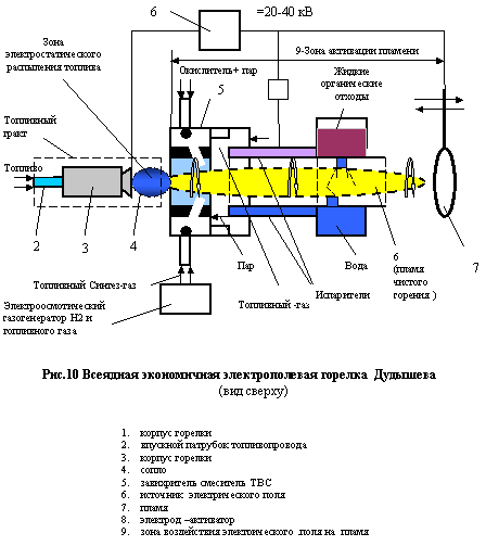
The proposed omnivorous Dudyshev vortex electric field burner is shown in a simplified form (without detailed disclosure of LEU HAU) in the block diagram ( Fig. 10 ). As our numerous experiments show, this unusual burner is efficient and very effective. This burner is multifunctional and provides simultaneous and significant activation of the fuel, its intensive electrostatic crushing, and at the same time, partial electroosmotic and intense electro-fired gasification of liquid fuel in the flame itself to the fuel synthesis gas from any of the composition and concentration of hydrocarbon aqueous solutions, emulsions of various hydrocarbon liquids, In t.ch. Diesel fuel, faeces, clean water in various proportions and combinations is achieved using electric fields with a voltage of 2-5 kV / cm . To do this, it is necessary to introduce aerosols or pairs of these aqueous hydrocarbon solutions of emulsions into the region of an electrified flame of a flame, for example, an ordinary natural gas. For this, after preparation and mixing, these hydrocarbon solutions, emulsions, first evaporate several turns of the pipeline, introduced into the flame region itself
Burners. A volumetric electrical charge is then introduced into this two-phase vapor-hydrocarbon fuel-aerosol environment, for example by means of a volumetric electrode, with a large contact area, then passed through a magneto-electric activator described above in this article. The steam so treated should be fed into an electrified flame, for example, through an electrostatic spray nozzle, with the heating and output of such an omnivorous electric burner into the operating mode, gradually reduce the supply of the share of the main fuel, for example natural gas, and add the fraction of the electrified steam. Gas can also be used high-voltage electrosmosis from capillary materials.
DEVICE FOR FUEL ECONOMY AND REDUCED TO EXHAUST GAS TOXICITY
MOTORS OF MOTOR TRANSPORT
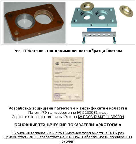
A steady increase in gasoline prices is a real disaster for ordinary Russian car owners. And the problems of ecology worry every citizen. Is there a development ready for operation on domestic cars, which resolves both these problems at once, cheaply and qualitatively. Yes it turns out that Samara has already developed, certified and produced a simple, cheap and efficient " Ekotop " device that allows solving these problems. Its essence consists in the vortex mixing and crushing of the fuel mixture of internal combustion engine. A simple and cheap fuel saving device ( 10-20% ), an increase in throttle response of any motor vehicle by 20-30% and a decrease in the toxicity of the exhaust gases of petrol carburetor ICEs (by an order of magnitude) have been developed, patented, tested and ready for serial production. The device is applicable for a wide class of serial vehicles with carburetor internal combustion engines ( VAZ, UAZ, GAZ , etc.). The device can be upgraded to any carburetor and injector ICE .
CONSTRUCTION OF THE VORTEX ECOTOPE
The device is a fairly simple mechanical design of the aerodynamic swirler ( Fig. 11 ), consisting of a thin body ( 8-13 mm with a carburettor bottom configuration and two rings - nozzles with tangential holes.) The device is installed under the engine 's carburetor. Operation is extremely simple.Work does not require care for it, so its lifetime is unlimited.
PRINCIPLE OF OPERATION OF ECOTOPE-VORTEX MIXTURE OF FUEL MIXTURE
The essence of the certified fuel saving device for combustion engines - " Ecotop " consists in the effective vortex mixing of fuel with air in the intake tract of the ICE . And in the partial dosed depletion of the fuel mixture in idling and afterburning modes of the ICE . As a result, the quality of the fuel assembly homogenization is improved, and as a result, the quality of combustion of the fuel mixture in the combustion chambers. And as a result there is a fuel economy and a reduction in the toxicity of VGV DVS. The advantage of the design is that it is extremely simple, and unlike the analogs, in our device there are no barriers on the way of the fuel mixture in the intake duct of the ICE . Therefore, the power and acceleration of the motor even increase, and the fuel fragmentation and turbulence and the fine mixing of the fuel mixture are carried out aerodynamically. The device has another unexpected and useful effect: it can be used after a little modification (Know-how) as a new effective anti-theft device in the case of introducing excess air through the Ecotope , in which an over-exerted fuel assembly can not ignite.
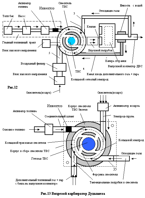
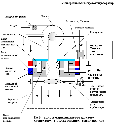
UNIVERSAL VORTEX FILLER - MIXER - FUEL MIXTURES ACTIVATOR
ECONOMIC VORTEX CARBURETOR OF DUDYSHEV
As you know, carburettors in automotive engines are designed to prepare a high-quality fuel mixture. However, they are still very complicated and imperfect, and therefore carburetor internal combustion engines ( ICE ) are now being replaced by actively injected ICE in which electromagnetic injectors controlled from an on-board computer perform the exact dosage and partial carburation of fuel. But in modern injector engines, fuel mixes very poorly with the oxidizer, because the injectors are in the immediate vicinity of the intake valves in the combustion chambers of these motors. As a consequence, poorly mixed fuel is not completely burnt and the ecology of the engine is far from ideal. Therefore, the injector motors are equipped with cellular catalytic converters of toxicity of exhaust gases ( VG ). And this neutralizer VG creates significant aerodynamic resistance - a "plug" in the exhaust path of the internal combustion engine , which leads to a deterioration in the operational, technical characteristics of the engine - to reduce the maximum engine power, acceleration and fuel consumption by 10-15% , depending on the mode of operation of the engine. Thus, the apparent complete rejection of efficient fuel assembly mixers-carburettors and the transition to injectors does not completely solve the problem of creating an ecologically perfect and economical ICE motor. Is there a way out of the impasse. Yes - it is necessary to combine the design of the injector unit with the modernized carburetor.
I propose a new type of combined injector-vortex carburetor - an activator of a fuel mixture that retains dignity and an injector and carburetor ICE , thanks to which it is possible to eliminate a significant obstacle to the exhaust gases of an ICE and permanently eliminate the exhaust catalytic converter's exhaust toxicity and at the same time ensure the economy and environmental cleanliness of the engine . However, the activation, for example, the electrification of fuel in the conventional intake path of the internal combustion engine is significantly weakened on the way to the combustion chambers and the activity of the fuel rapidly weakens from contact of such electrified fuel with the metal wall of the metal carburettor and the intake manifold. In order to eliminate the loss of the activation capacity of the electrified fuel, I propose to additionally electrically insulate the internal The surface of the swirler and the inlet duct, for example PVC pipes - but still implement the principles of activation, injection and vortex mixing of the fuel assembly components in this unusual carburettor ( Figure 1.2 ). It is possible to radically improve the technology of preparing a fuel mixture in any thermal combustion engine by constructively combining a fuel activator - filter = air ozonator and central fuel injector and vortex mixer fuel mixture components, Expected fuel economy from the introduction of this innovation - 20-30% and improved environmental cleanliness of exhaust gases ( VG ) at Euro 3, 4 . Generally without external cellular neutralizer of toxicity of VG .
The universal injector-vortex carburetor is simplified in Fig . 12-14 . Its principle of operation is to combine the principles of the work of the Ecotope, the fuel activator and the electrostatic nozzle in one device.
COMBINED NON-CONTACT FUEL BLOCK
"ELECTROCULON FUEL PUMP - ELECTROSTATIC FORWARD-CANDLE"
At the present time, the fuel path of the injector ICE is very complex and unreliable. It includes a high-pressure fuel pump, an electro-magnetic fuel injector, and many other things including numerous unreliable sensors. The principle of creation of explosive electron emission of an electric charge in a dielectric fluid in combination with the Coulomb repulsive forces = ensures the realization of a low-cost effect of the emergence of an intense dielectric coulondore of a dielectric liquid-the "Dudyshev effect" -for example, fuel jets, which makes it possible to create a unique hybrid of a combined device. "The noncontact high-efficiency Electro-Coulomb fuel pump -electrostatic nozzle-el. Spark plug ", which fits perfectly into the overall layout in the new injector engines, for example, direct injection of fuel into the combustion chambers. In order to improve the homogenization of ballasted and depleted fuel assemblies, it is advisable to apply additionally and the principle of vortex mixing and activation of fuel and other components of the fuel assembly, ie, to perform a vortex mixing of the oxidizer with the exhaust gases, in order to ensure the quasi-turbocharging of such a unique efficient and economical injector thermal motor .
Moreover, it is very effective in this case-for the operation of ICE on superweaked FAs it is magnetic spark plugs, electrostatic fuel atomisation devices and magnetoelectric fuel activators, described above.
The physics and anomalous energetics of the formation of a non-contact electro-rheological pumping effect of a high-pressure jet of fuel in a pulsed electric field (the Dudyshev effect) is described in more detail in my articles / 2,4 /.
A hybrid energy-saving fuel supply device for such a combined unit "electrostatic pump-electromagnetic spark plug -electrostatic nozzle" -the new system for preparing and injecting fuel directly into the combustion chambers of the internal combustion engine or into the intake duct of the ICE is shown in Fig. 15 (illustration to the invention / 5 /).
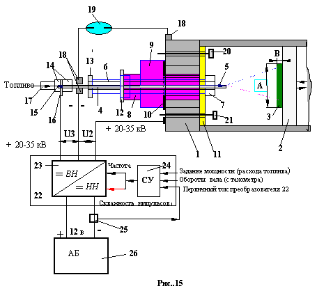
1. combustion chamber of internal combustion engine
2. the piston
3. Corrosion-resistant disc in the center of the piston (A-diameter, V-thickness)
4. Central metal removable electrode with external screw thread (4-1-its pointed end with corrosion-resistant coating)
5. hollow capillary through hole in electrode 4
6. Electrical insulated plug sleeve
7. metal case of electric candle
8. Hexagon socket of the candle case for screwing (for a wrench)
9. sealing gasket (copper)
10. fixing sealing sleeve
11. Electrical insulating gasket (cermet) with holes for valves and central electrode 4
12. Fixation sealing sleeve of the candle body
13. The clamping sealing sleeve of the electrical insulator
14. Electrostatic bushing of electrostatic pump
15. Adjustable diaphragm at the entrance of a hollow central electrode
16. Locking control electrode of electrostatic pump
17. fuel pump with fuel line
18. high-voltage terminals
19. High-voltage spark gap indicator of high voltage
20. Internal combustion engine inlet
21. Internal combustion engine exhaust valve
22. Adjustable high-voltage high-frequency (20-30 kHz) inductive-semiconductor converter of the onboard voltage (+ 12V) into a constant voltage (20-35 kV)
23. power boosting adjustable voltage converter of blocking-generator type with control over frequency and duty cycle and parametric stabilization by input voltage and temperature
24. A scheme for controlling the frequency and the duty cycle of the modulating voltage of the converter 23, comprising a motor speed sensor, a primary current consumption sensor of the unit 23, a power controller (accelerator pedal), and others, and including a pump mode optimizer
25. Primary current sensor 9 with separate output in terms of constant and alternating current components
26. An on-board power source, for example, a rechargeable battery (AB)
Conclusions :
1. An ecologically clean complex technology for radical end-to-end fuel activation, ignition and combustion with the use of strong electric and magnetic fields of low power was developed and approved. The total fuel economy during the implementation of the technology in full -40-60% with a simultaneous significant improvement in the environmental performance of combustion processes of water-fuel emulsions
2. New methods and devices of radical fuel economy on motor transport and in heat power engineering have been patented and tested.
3. The proposed new electro-magneto-firing technologies and methods of activation of combustion processes are based on new physical effects of interaction of electric and magnetic fields on substances and flames discovered and investigated by me.
4.This technology of invention and development in the case of their mass introduction will significantly reduce the severity of global energy and environmental problems, created mainly by heat and power and transport.
LITERATURE
1. Dudyshev V.D. "Electro-fire technology is an effective way of solving energy and environmental problems-" Ecology and Industry of Russia ", No. 3/97
2. VDDudyshev, "How to save civilization and nature from global environmental pollution?" - "Ecology and Industry of Russia" No. 11 / 97g.)
3. Dudyshev V.D. The new electric fire technology of environmentally friendly combustion - "New Energy" №1,2003.,
4. V.Dudyshev. New methods for extracting and converting the latent potential energy of an electric field into kinetic energy and electric power - New Energy, No. 4/2003.
5. V.Dudyshev. Methods for converting the energy of electrohydraulic impact and cavitation of liquid into heat and other types of energy- "New Energy", 1/2005.
6. V.Dudyshev. New methods for extracting and converting the latent potential energy of the electric field into kinetic energy and electricity - "New Energy", No. 4/2003
7. Dudyshev VD The phenomenon of effective charge-mass transfer in a pulsed electric field and its use in a new electrohydraulics of a new generation- "Novaya Energetika", 2/2004.
8. V.Dudyshev. Methods for converting the magnetic energy of permanent magnets and the principles of operation of magnetic field energy converters - "Novaya Energetika" 4/2004
9. V.Dudyshev. A method of supplying and igniting a fuel mixture in an internal combustion engine and a device for implementing it is RF patent number 21160380
10. Dudyshev V.D. The method of burning fuel and the device for its implementation is -Pat RF No. 2160414
11. Dudyshev V.D. "Method of controlling flame combustion" -pat. Of the Russian Federation No. 22017219
12. VD Dudyshev. Method of intensification and control of flame combustion "-pat. RF No. 2125682 with the priority of 06/06/95
13. Dudyshev V.D. The method of intensification of combustion of a flame in a furnace of a boiler plant-pat. RF No. 2079766 with a priority of 14.06.95 (electric-fire method)
14. VDDudyshev. "Method of internal purification of exhaust gases of ICE" Patent of the Russian Federation No. 2165031
15. Dudyshev V.D. "A way to intensify and control the burning of a flame" Pat. RF No. 2125682
16. Dudyshev V.D. "Method for controlling a heat engine" Patent of the Russian Federation No. 2134354
17. V.Dudyshev. "A way to intensify the operation of ICE" Patent of the Russian Federation No. 2135814
18. V.Dudyshev. "Method for reducing the toxicity of motor vehicle exhaust" - Patent of the Russian Federation No. 2117179. with priority from 20.02.96 (electric-fire method)
19. V.Dudyshev. Method of electromechanical energy conversion -Pat RF № 2182398
20. VD Dudyshev. Method for converting the energy of an electrohydraulic shock - RF Pat. No. 2157893
21. Dudyshev VD Ecological safety of motor transport - "Ecology and industry of Russia" №5 / 97 g
22. V.Dudyshev. Perspective technical developments and inventions for the environmental improvement of vehicles = "ECIP" No. 12/98.
23. Dudyshev V.D. Problems and ways of ecological improvement of domestic motor transport - "ECIP" № 11/98.
24. Dudyshev V.D. "Ecologically clean motor for motor vehicles" - in the "New Technologies" magazine No. 2/2001 in Samara
25. V.Dudyshev. Fuel economy and reduction of toxicity of gasoline engines- "Ecology and Industry of Russia" May, 2003
26. Dudyshev V.D. "A new effect of cold evaporation and dissociation of liquids based on the capillary electroosmotic effect" in the zh-le "New Energy" "№ 1/2003.
27. V.Dudyshev. Cheap fuel gas and hydrogen from water faeces solutions - "Ecology and Industry of Russia", August 2004.
ATTENTION !
Drawings of pilot plants and explanations to the invention are the author's know-how
Are provided on REQUEST on a commercial basis
print version
Author: Valery Dudyshev
PS The material is protected.
Date of publication 27.02.2005гг
![]()

Comments
When commenting on, remember that the content and tone of your message can hurt the feelings of real people, show respect and tolerance to your interlocutors even if you do not share their opinion, your behavior in the conditions of freedom of expression and anonymity provided by the Internet, changes Not only virtual, but also the real world. All comments are hidden from the index, spam is controlled.