
| Start of section
Production, amateur Radio amateurs Aircraft model, rocket-model Useful, entertaining |
Stealth Master
Electronics Physics Technologies Inventions |
Secrets of the cosmos
Secrets of the Earth Secrets of the Ocean Tricks Map of section |
  |
| Use of the site materials is allowed subject to the link (for websites - hyperlinks) | |||
Navigation: => |
Home / Table of Contents / Table of Contents / |
|
UNIVERSAL BURNER WITH ROTATING ELECTRO-ARC
![]()
Dudyshev Valery Dmitrievich, Russia, Samara
Samara Technical University
Application for the invention of the Russian Federation No. 20050 97452
MKI F23D14 / 02
H05H1 / 26
A useful model refers to burners for power boilers, gas turbine and combined-cycle plants and any furnace for industrial furnaces.
The closest device of the same designation to the claimed utility model for the set of characteristics is a burner for burning fuel, containing a body, a fuel line connected to a nozzle (Prototype - RF Patent No. 2243447 ).
With all the advantages of the prototype, the existing burner has reduced reliability due to the phenomenon of deposit, reduced fuel efficiency and reduced efficiency due to the impossibility of ignition of depleted fuel mixtures and as a result resulting in incomplete combustion of fuel mixture, fuel overexpenditure and high toxicity of exhaust gases.
The technical result of this utility model is that it is further provided with an electrical insulator located in the burner housing outside the fuel pipe and nozzle and obtaining the effect of electric arc rotation when there is a constant magnetic field in the burner of the source, for example a permanent magnet or permanent magnet, and in the formation between The nozzle of the injector of the fuel pipe and the conical diffuser of the torch body of the traveling concentric arc of ignition, which leads to an increase in the intensity of ignition and combustion of the fuel mixture, and as a result, to a decrease in fuel consumption and improvement of the ecological purity of the exhaust gases. Additional positive effects of such a universal burner consist in its efficient start-up and the possibility of the burner operating on depleted fuel mixtures, and in improving its reliability and service life.
This technical result is achieved by the addition of an electrical insulator placed in the burner casing outside the fuel line and the injector, a source of a permanent magnetic field made in the form of a permanent electromagnet or a permanent magnet located in the burner body containing the body, the fuel line connected to the injector, So that the magnetic field lines of the magnetic field source cross the working gap between the nozzle outlet nozzle and the conical diffuser of the burner housing, for example, a permanent electromagnet or permanent magnet is mounted on the outer part of the burner housing, and the fuel line of the burner is the magnetic circuit closing magnetic lines of force in the above-mentioned operating The burner gap, which leads to the formation between the outlet nozzle of the injector and the conical diffuser by the torch body of the rotating electric arc-plasma.
In Fig. 1, 2, a universal burner is shown comprising a metal casing 1 , a fuel line 2 with an electrical insulator 3 , a nozzle of a fuel injector 4 , a conical diffuser 5 of the casing 1 , an annular permanent magnet 6 coaxially located from the outer part of the burner casing 1 , a combustion chamber 7 , magnetic power Line 8 of the magnetic dipole of the annular permanent magnet 6 closing its magnetic poles between the conical diffuser 5 of the burner body 1 and the nozzle of the injector 4 of the fuel pipe 2 where an electrical discharge occurs as a rotating electric arc 9 .
PRINCIPLE OF WORK OF THE UNIVERSAL BURNER
The fuel line 2 of the burner from the high-voltage source (not shown) is fed with a constant, regulated in frequency and amplitude, a constant electric current. The source of the magnetic field 6 , for example, an annular permanent magnet 6, creates in the spark plug a magnetic field of the dipole type of a given intensity. The magnetic lines of force 8 of the permanent magnet 6 are closed through the fuel line 2 , the nozzle of the injector 4 , the electric arc 9 , the conical diffuser 5 of the housing 1 . Due to the intersection of the electric arc 9 by the magnetic power lines 8 , the latter comes into rotation as a result of the force interaction of the magnetic field of the annular permanent magnet 6 with the electric current flowing in the electric spark 9 between the nozzle of the injector 4 of the fuel pipe 2 and the conical diffuser 5 of the housing 1 . The regulation of the speed of rotation of the electric arc is provided by changing the parameters of the electric current in arc 9 and the magnitude of the magnetic induction from the permanent magnet 6 . The reverse rotation of the electric arc is provided by rotating the permanent ring magnet 180 degrees . In the case of a permanent electromagnet, the reversal of rotation of the electric arc 9 is effected by changing the polarity of the voltage on its winding. Due to the rotation of the electric arc, a plasma spot forms in the gap between the conical diffuser 5 of the housing 1 and the nozzle of the injector 4 of the fuel pipe 2 . As a result, the intensity of ignition and improvement of combustion of the fuel mixture in the combustion chamber 7 is increased, and as a result, the fuel consumption and the environmental purity of the exhaust gases are improved. Additional positive effects of such a universal burner consist in its efficient start-up with ignition of the burner, the possibility of burner operation on depleted fuel Mixtures, and in increasing its reliability and service life.
CLAIM
A universal burner comprising a housing, a fuel line connected to a nozzle, characterized in that it is provided with an electrical insulator located in the burner housing on the outside of the fuel pipe and injector, and is provided with a constant magnetic field source, for example a DC magnet or permanent magnet located on the burner So that the magnetic field lines of the magnetic field source cross the working gap between the nozzle outlet nozzle and the burner body.
|
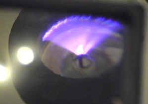
I thank unique properties of such method of ignition of any fuel mixes - the torch with rotation of an electric arc becomes out of competition on profitability and ecological compatibility . In Fig. From the left is shown a photo of the experiment with the rotation of the electric arc in the magnetic field of the annular permanent magnet. |
ESSAY
A useful model refers to burners for power boilers, gas turbine and combined-cycle plants and any furnace for industrial furnaces.
The technical result of this utility model is that it is further provided with an electrical insulator located in the burner housing outside the fuel pipe and nozzle and obtaining the effect of electric arc rotation when there is a constant magnetic field in the burner of the source, for example a permanent magnet or permanent magnet, and in the formation between The nozzle of the injector of the fuel pipe and the conical diffuser of the torch body of the traveling concentric arc of ignition, which leads to an increase in the intensity of ignition and combustion of the fuel mixture, and as a result, to a decrease in fuel consumption and improvement of the ecological purity of the exhaust gases. Additional positive effects of such a burner consist in its efficient start-up and the possibility of operating the burner on depleted fuel mixtures, and in improving its reliability and service life.
This technical result is achieved by adding to the known device, a burner comprising a housing, a fuel line connected to the injector, an electrical insulator located in the burner housing outside the fuel pipe and the injector, a permanent magnetic field source in the form of a permanent electromagnet or permanent magnet located So that the magnetic field lines of the magnetic field source cross the working gap between the nozzle outlet nozzle and the conical diffuser of the burner housing, for example, a permanent electromagnet or permanent magnet is mounted on the outer part of the burner housing, and the fuel line of the burner is the magnetic circuit that closes the magnetic lines of force in the above- The burner gap, which results in the formation of a torch body of a rotating electric arc between the outlet nozzle of the injector and the conical diffuser.
print version
Author: Valery Dudyshev
PS The material is protected.
Date of publication on February 21, 2005
![]()

Comments
When commenting on, remember that the content and tone of your message can hurt the feelings of real people, show respect and tolerance to your interlocutors even if you do not share their opinion, your behavior in the conditions of freedom of expression and anonymity provided by the Internet, changes Not only virtual, but also the real world. All comments are hidden from the index, spam is controlled.