MIT Guide to picking locks opening
Chapter 2 - How to open the key lock
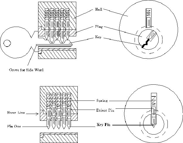
This chapter contains the main characteristics of cylinder locks, and the vocabulary used in this manual. The terms used to describe locks and lock parts vary from manufacturer to manufacturer and from city to city, so even if you are already familiar with the basic principles of operation of locks, look at Fig. 2.1 , which contains the vocabulary.
Understand how the castle during his opening key - this is only part of what you need to know. You also need to know what is happening with the lock during opening. Ch. 3 and 5 contain a description of the models that will help you understand the reaction to the opening of locks.
Figure 2.1 contains translations of these locks. The key is inserted into the groove (keyway), located in the cylinder (plug). The groove has projections (wards). The protrusions limit the number of keys that can be inserted into the cylinder. The cylinder can be rotated when the key is inserted into the requested it. Non-rotating part of the castle is called the body (hull). First pin, which concerns a key called pin № 1. The remaining pins are numbered in ascending toward the rear of the lock.
The proper key lifts each a pin pair until the gap between the key pin (key pin) and the guide pin (driver pin) reaches the sheer line (sheer line). When all the pins are in that position, the cylinder can be rotated and the lock opens. If the groove is inserted the wrong key, some pins protrude between the housing and the cylinder and prevent the rotation of the cylinder.

Fig. 2.1. Cylinder lock device


Comments
Commenting, keep in mind that the content and the tone of your messages can hurt the feelings of real people, show respect and tolerance to his interlocutors, even if you do not share their opinion, your behavior in terms of freedom of speech and anonymity offered by the Internet, is changing not only virtual, but real world. All comments are hidden from the index, spam control.