Guide MIT on the opening of locks picklock
Chapter 5 - The Vertical Model
The horizontal lock model can explain effects in which more than one pin is involved, but in order to explain the behavior of one pin in detail, another model is needed. The vertical model shows the relationship between the rotational torque applied to the cylinder and the force required to lift each pin. To understand this attitude is extremely important.
To "feel" what happens to the lock during its opening, it is necessary to know how the rotational moment exerted by the lever on the cylinder and the pressure exerted by the master key on the pins affect the movement of the pin. This is conveniently demonstrated by a graph showing the relationship between the minimum pressure required to lift the pin and how far the pin is displaced from its original position. At the end of this chapter, a force chart drawn up based on the vertical model will be compiled.
Fig. 5.2 shows the position of the pin after giving the cylinder a torque. The following forces act on the guide pin: friction on both sides, contact force of the spring from above and contact force of the key pin from below. The amount of force that is attached to the master key determines the contact force from the bottom.
Resistance of the spring increases as the pins push up, but this increase is insignificant, so we will assume that the force of the spring is constant in all the displacements of the pin that we are considering. The pins will only move when you apply enough force to overcome the spring resistance. The frictional force of the pins is proportional to how closely the guide pin adjoins the walls of the holes in the cylinder and in the housing, which in our case is proportional to the rotational torque. The more torque you give to the cylinder, the more difficult it is to bring the pins into motion. To make the pin move, you need to apply pressure greater than the sum of the spring and friction resistances.
As the pins are pushed into the housing, the key pin begins to experience friction, similar to that of the guide pin in its original position. See Fig. 5.4 . Thus, to bring the pins into motion before and after the rotation line, approximately the same pressure is required. As the torque increases, the required pressure also increases. On the rotation line, the pressure rises sharply, because the key pin strikes the body. All described forces are graphically represented in Fig. 5.5 .
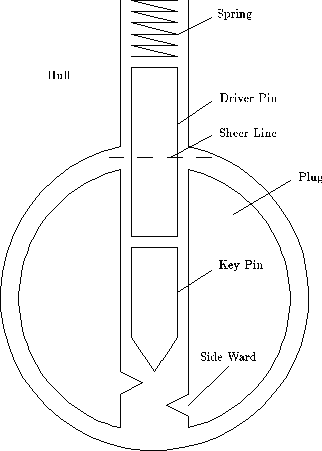
Fig. 5.1 . Vertical model
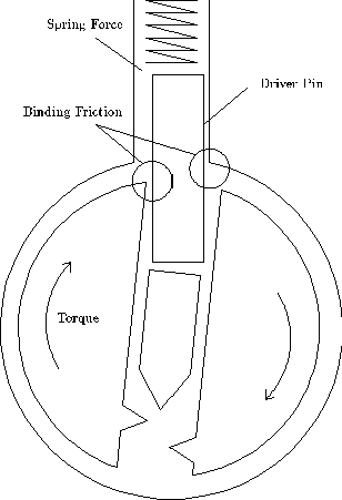
Fig. 5.2 . The pin contacts the wall of the hole
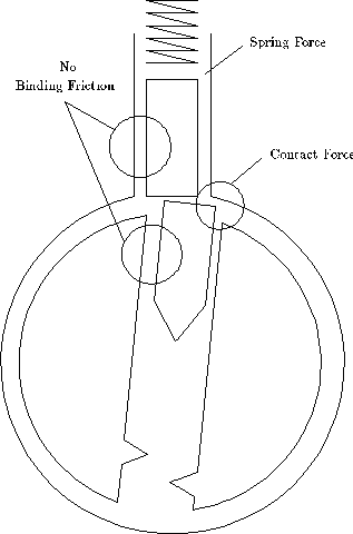
Fig. 5.3 . Pins on the rotation line
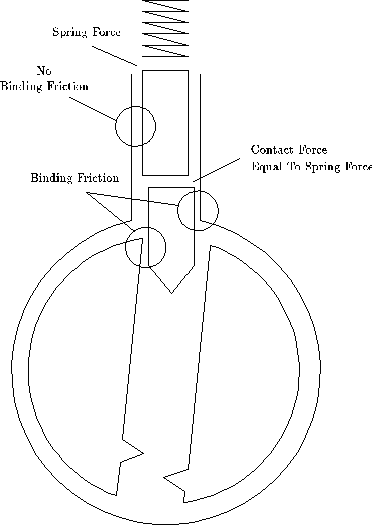
Fig. 5.4 . Key pin enters body
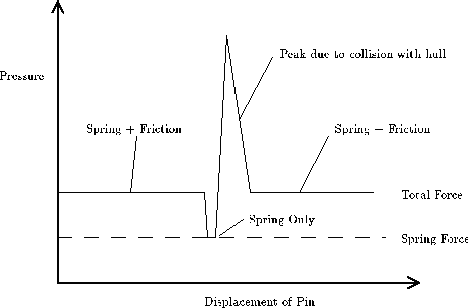
Fig. 5.5 . The pressure necessary to bring the pins into motion


Comments
When commenting on, remember that the content and tone of your message can hurt the feelings of real people, show respect and tolerance to your interlocutors even if you do not share their opinion, your behavior in the conditions of freedom of expression and anonymity provided by the Internet, changes Not only virtual, but also the real world. All comments are hidden from the index, spam is controlled.